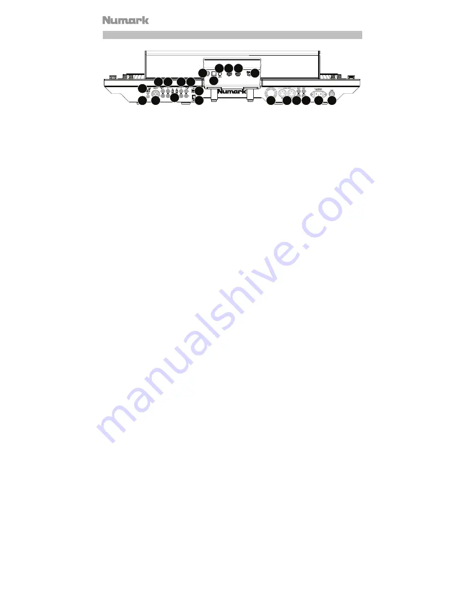
Numark NS7III User Manual Download Page 22


22 


Rear Panel 


1 2

3

4

5

6

7

8 9

11

20

12 13

14

14

16

17 18

19

16

15

10


1.


NS7III Power Input:

 Use the included power cable to connect NS7III to a power outlet. 

While the power is switched off, plug the cable into NS7III first, then plug the cable into a 
power outlet.  

2.


NS7III Power Switch:

 Powers NS7III on and off. Power on NS7III after all input devices 

have been connected and before you turn on amplifiers. Turn off amplifiers before you turn 
off NS7III. 

3.


USB Port:

 Use the included small display USB cable to connect this USB port to the 

NS7”


USB


port

 on the display. 

4.


Power Output 

(

DC Out

)

Use the included small display power cable to connect this 

output to the 

display power input 

(

DC In

). 

5.


Display Power Input 

(

DC In

)

Use the included small display power cable to connect this 

input to the 

power output 

(

DC Out

) on NS7III. 

6.


Cable Restraint:

 You can secure the display power cable to this restraint to help prevent 

disconnecting it accidentally.


7.


Display Power Switch:

 Powers the display unit on and off. 

8.


USB Port 

(

NS7

)

:

 Use the included small display USB cable to connect this USB port to the 

USB port

 on NS7III.


9.


USB Port 

(

USB In

)

:

 You can connect an optional USB hard drive (not included) to this 

powered USB port.


10.


Display USB Port 

(

To PC

)

:

 Use the included USB cable to connect this USB port to your 

computer. 

11.


Master Output 

(

XLR

)

:

 Connect this low-impedance XLR output to a PA system or powered 

monitors. The level of this output is controlled with the Master knob on the top panel.  

12.


Master Output 

(

RCA

)

:

 Use standard RCA cables to connect this output to a speaker or 

amplifier system. The level of this output is controlled by the 

Master

 knob on the top panel. 

13.


Booth Output 

(

RCA

)

:

 Use standard RCA cables to connect this output to a booth monitoring 

system. The level of this output is controlled by the 

Booth

 knob on the top panel.  

14.


Line

/

Phono Inputs 

(

RCA

)

:

 Connect your audio sources to these inputs. These inputs can 

accept both line and phono-level signals.  

15.


Line

/

Phono Switch:

 Flip this switch to the appropriate position, depending on the device 

connected to the 

Line

/

Phono Inputs

. If you are using phono-level turntables, set this 

switch to 

Phono

 to provide the additional amplification needed for phono-level signals. If 

using a line-level device, such as a CD player or sampler, set this switch to 

Line

16.


Line Inputs 

(

RCA

)

:

 Connect line-level devices, such as CD players, samplers or audio 

interfaces, to these inputs. 

Summary of Contents for NS7III

Page 1: ...User Guide English 2 23 Gu a del usuario Espa ol 24 45 Guide d utilisation Fran ais 47 70 Guida per l uso Italiano 71 93 Benutzerhandbuch Deutsch 94 117 Appendix English 118 119...

Page 2: ...play Unit Display USB Cable Display Power Cable Serato DJ Software download USB Cable Power Cable Quickstart Guide User Guide download Safety Warranty Manual Support For the latest information about t...

Page 3: ...on a flat stable surface for operation Ensure unit has adequate air flow to all ventilation ports especially if installed in a case 2 Place the platter onto NS7III by aligning the pins in the bottom...

Page 4: ...y unit 2 Using the small display USB cable included connect the NS7 USB port on the display unit to the USB port on NS7III s rear panel 3 Using the small display power cable included connect the displ...

Page 5: ...t sources 2 NS7III and display unit 3 output devices When ending a session turn off 1 output devices 2 NS7III and display unit 3 input sources 5 Using a standard USB cable included connect the To PC U...

Page 6: ...ad The current position in a track from where audio will play When you select a track and begin playing the Audio Playhead will usually start from the beginning and stop at the end Hot Cue Point A mar...

Page 7: ...nel s controls will only send MIDI information when its Input Selector is set to PC Important Do not set more than one channel s Input Selectors to Mic2 doing so can cause unwanted feedback or distort...

Page 8: ...the beginning of the track 23 Sync Press this button to automatically match the corresponding Deck s tempo with the opposite Deck s tempo and phase Press and hold Shift and press this button to deacti...

Page 9: ...orange When the button is unlit the first press will always select Hot Cue Mode Hot Cue Mode Each pad assigns a Hot Cue Point or returns the track to that Hot Cue Point When a pad is unlit you can as...

Page 10: ...he track to one of your saved loops You create and save a loop using Pads 5 8 the bottom row The pad layouts for the two banks are identical o To create a loop press Pad 5 to set the Loop In Point and...

Page 11: ...ays select Slicer Mode Important Your track must have a set Beat Grid for Slicer Mode or Slicer Loop Mode to work Slicer Mode The eight pads represent eight sequential beats Slices in the Beat Grid Th...

Page 12: ...you stop the action the track will resume normal playback from where it would have been if you had never done anything i e as if the track had been playing forward the whole time Press and hold Shift...

Page 13: ...hift and then press Fwd to sort the current Library Crate Panel View by album Press and hold Shift and then press Back to sort the current Library Crate Panel View by track number 45 Crates Press this...

Page 14: ...and hold Shift and then press this button to switch between Single FX Mode and Multi FX Mode 54 Beat Knob Turn this knob to set the Time Division for the selected effects 55 FX Assign Use these button...

Page 15: ...play on either deck To enter Library View immediately turn the Scroll Knob After not touching the Scroll Knob for 5 seconds the display will return to Waveform View To load a track to a deck from Libr...

Page 16: ...ft of the currently loaded track 7 Pitch Range This is the current range of the deck s Pitch Fader Press Range Keylock on that deck to adjust the range of its Pitch Fader to 8 16 or 50 8 Pitch Adjustm...

Page 17: ...t in either mode press and hold Shift and then press the FX Button under the effect name Alternatively press and hold Shift and then turn the FX Knob under the effect name to move quickly through the...

Page 18: ...the track list and crate list press the Scroll Knob or use the Back Fwd button To expand or collapse a crate that has subcrates in the crate list press the Back Fwd button 1 Crate List Name This is t...

Page 19: ...loaded track is playing To adjust this value move the deck s Pitch Fader This number is not affected by temporary pitch bends using the Pitch Bend buttons or the platter 7 Remaining Time This is how...

Page 20: ...er knob each which corresponds to the main parameter of that effect To adjust each effect turn the FX Knob below it In Single FX Mode the view will show one effect name with three parameter knobs To a...

Page 21: ...5 Crossfader Assign Routes the audio playing on the corresponding channel to either side of the crossfader A or B or bypasses the crossfader and sends the audio directly to the Program Mix center Off...

Page 22: ...III 9 USB Port USB In You can connect an optional USB hard drive not included to this powered USB port 10 Display USB Port To PC Use the included USB cable to connect this USB port to your computer 11...

Page 23: ...8 Mic 2 Input 1 4 6 35 mm Connect a 1 4 6 35 mm microphone to this input Microphone controls are located on the top panel on any channel whose Input Selector is set to Mic2 19 Motor Torque Flip this s...

Reviews: