


6
08. 10. 20. Document Number 670506
Nuaire |
Western Industrial Estate
|
Caerphilly
|
CF83 1NA
|
nuaire.co.uk
TRA / TRC / TRM
Installation Manual
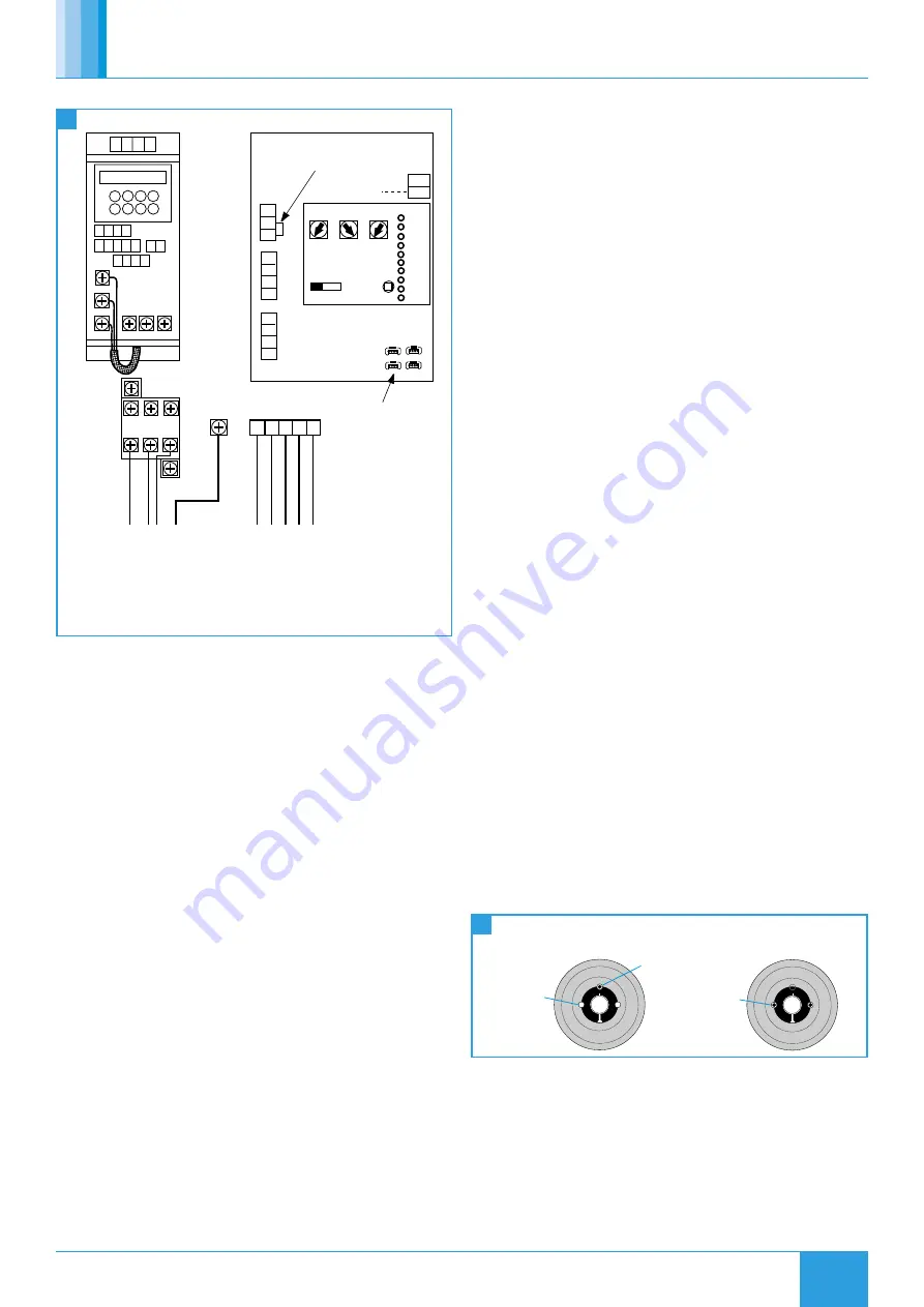
4.3.5 Three Phase, Ecosmart Speed Control
N
L
SL
Max SL run on
Min
Trickle
Test
0 1
Pwr
Standby
Fan 1
Heating
Cooling
Fan 2
Fault
Tx
Rx
Frost
Ecosmart
Earth
D
AMPER
L3
L1
N
E
FA
ULT
RUN
L2
Mains supply connections
400V 50Hz 3ph + Neutral
via local isolator
3 5
1
4 6
2
(U)
(V) (W)
L3
L1 L2
E
(U)
(V) ( W)
L3
L2
L1
12 13
15
14
5
9
6 7 8
10 11
2
1
3 4
A1
A2
CON
TA
CTER
0V
0-10V
BMS signal
'NET' connection
E N L1 L2 L3
U V W E
DP
CL
N
RET
Connections to fan via screened
power cable. Purpose made glands
are provided to earth the screening
Remove this link if:
1: A switched live signal is connected
2: A ES-PIR, ES-TC or BMS Signal is connected
Note: Internal connections
between the supply
terminals, output
contactors the PCB and
inverter are made at
the factory
Note: The Ecosmart control box is a seperate item packed
individually. See installation document 671193 for details
of Ecosmart Control (ES-ISC).
11
Three Phase, Single Speed (TRA100H-43 Only) Wiring Diagram
5.0 MAINTENANCE
It is important that maintenance checks are recorded and that the
schedule is always adhered to, in all cases, the previous report should
be referred to.
Before attempting to carry out any work; ensure the unit and speed
control, if fitted, are electrically isolated.
Do not operate the unit with the cowl removed. The impeller will
continue to rotate after the supply has been disconnected - allow
sufficient time for the impeller to come to rest.
Remove the cowl to gain access to the moving parts.
The unit is not
weather tight when cowl is removed.
TRA (Axial)
The impeller is accessible immediately and can be removed
if required.
TRC (Centrifugal)
Motor/impeller bridge assembly can be removed
after releasing the 4 or 6 screws holding the bridge support. On this
unit the impeller cannot be removed from the motor.
TRM (Mixed flow)
Motor/impeller bridge assembly can be removed
after releasing the 4 or 6 screws holding the bridge support. Invert the
bridge and remove impeller if required
5.1 Routine Maintenance
•
Generally clean all areas of unit and treat any areas of corrosion.
•
Check the impeller rotates freely and does not foul the fan plate.
•
Remove all dust and dirt from impellers, be especially careful not
to disturb balance weights.
•
Check that bird guards (if fitted) / safety grilles are secure and free
of obstruction.
•
Check anti-backdraught shutters operate correctly.
•
Inspect the condition and tightness of all fittings.
5.2 Annually
•
Thoroughly inspect the unit and its components for corrosion,
acting immediately to treat/restore any damaged areas.
•
Check motor for undue wear, signs of overheating and apply
winding insulation and continuity tests
•
Inspect all bolts, fixings and electrical terminals for security.
•
Check resilient mounts and replace any that show signs of wear or
deterioration.
5.3 Impeller Cleaning
A build-up of dust/dirt may be removed by brushing carefully with a
stiff brush. Take care not to damage or distort the impeller blades. If the
impeller is too badly fouled to allow cleaning in situ, proceed as follows:
•
Remove the impeller.
•
Remove all loose dirt using a stiff brush.
•
Sponge the impeller with warm soapy water.
Do not use solvents
or caustic fluids.
•
Rinse thoroughly with clean water and wipe dry.
5.4 Impeller Removal
5.4.1 TRA (Axial)
•
Knock up the tab washer and remove the retaining screw.
•
Remove the impeller from the motor shaft.
•
Retain the motor shaft key.
•
Replacement is the reversal of the above procedure.
5.4.2 TRC (Centrifugal)
On this type of unit the impeller cannot be removed from the motor.
Cleaning of the impeller must be carried out in situ.
5.4.3 TRM (Mixed Flow)
On this type of unit the impeller is held in place by a taper lock fixing.
To release the impeller:
•
Remove the grub screws on each side of the slit.
•
Lightly lubricate one of the grub screws and insert it into the
threaded hole opposite the slit (A).
•
Carefully tighten the grub screw until the tapers ‘break’ allowing
removal of the impeller.
•
Remove the impeller.
12
Mixed Flow Impeller Taper Lock Details
A
1. Remove both
grub screws
2. Insert grub
screw and tighten
Fit both grub
screws and
tighten
B
5.5 Impeller Replacement (TRM Only)
Place the impeller over the shaft and locate the taper lock in the
impeller. Insert and tighten the two grub screws into the tapped holes
either side of the slit (B).


