


2
Remove the unit cover, retained by two M4 screws (see fig 3).
Pull out the electronic control module approx. 15mm to disengage
the electrical spade contacts (see figure 5).
Note the unit control module speed adjustment on the control
module (figure 7) must be set at 25% for low (NORMAL)
speed.
The standard setting as supplied from the factory for high BOOST
speed is 100% and will give the optimum performance for most
applications. See ‘Adjusting the NORMAL and BOOST speeds’.
Unscrew the four, M5 x 35 captive blower retaining screws.
Remove the blower assembly complete with the electronic control
module (see figure 6).
Mark the four main unit fixing positions on the mounting surface.
Drill and plug the surface to accept the unit fixings (the fixing
centres are shown in figure 6).
NOTE: For wall mounting ensure that the cable access is on
the left (as shown in the drawing).
Select a suitable location for the remote switch supplied. Prepare
the mounting surface to accept the standard MK switch box and
arrange the box in position. Wire the switch to the fan terminals
3 and 1 (these are low voltage terminals).
Offer the unit up to the surface and bring the mains wiring and
remote switch wiring through the cable entry grommet provided
in the back of the unit casing.
Connect the ductwork to the outlet spigot and fix the unit to the
surface. Any subsidiary inlet ductwork can now be connected to
the unit.
Fitting a subsidiary
inlet spigot
The subsidiary inlet spigots
supplied will replace any of
the four standard unit inlets.
(See Figure 1).
Select the inlet position required.
With the front cover removed,
press out the standard inlet
grille. Locate the inlet spigot
supplied into the aperture and
press into position.
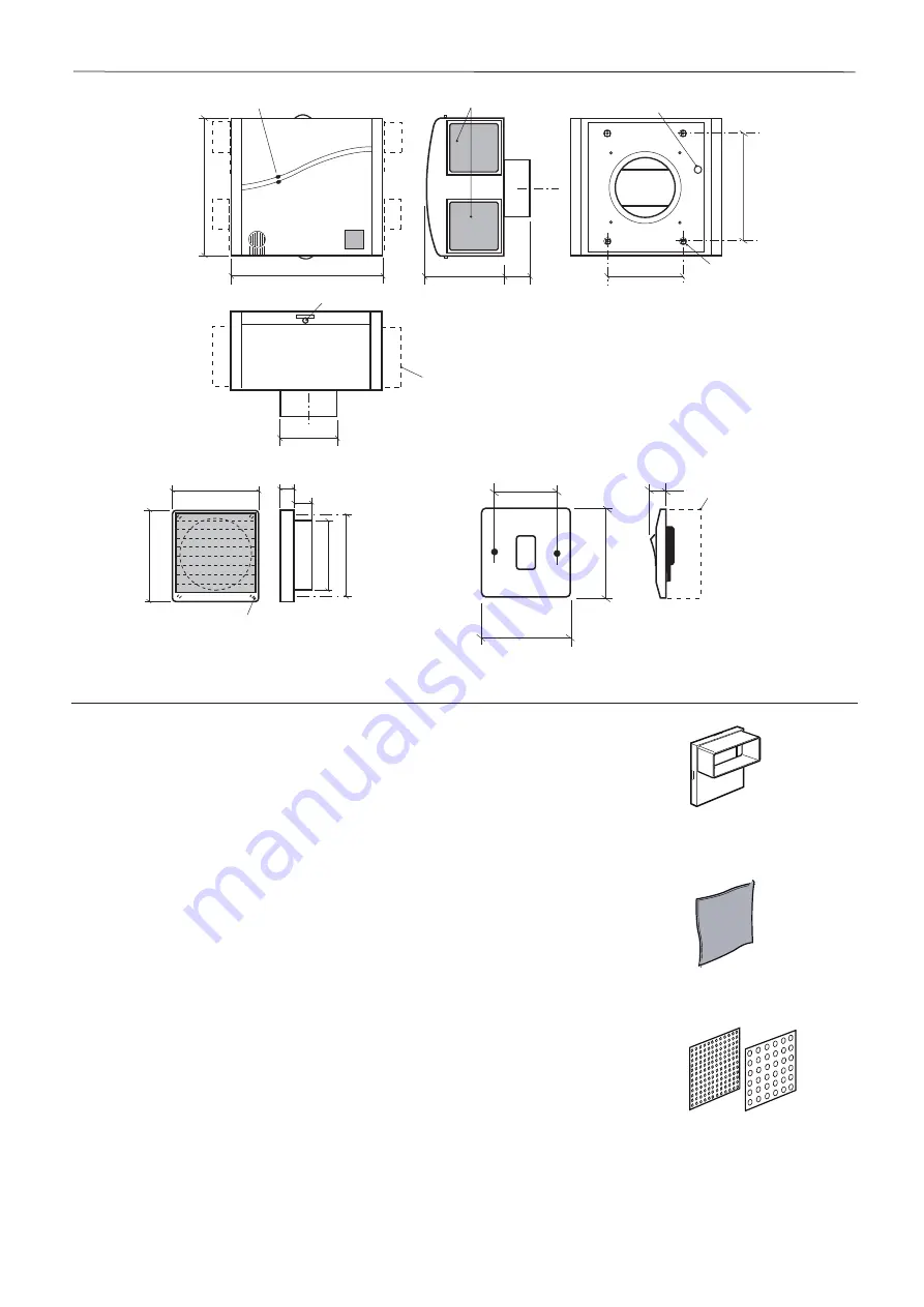
Dimensions
Figure 3.
Installation and Maintenance
MEV-B Continuous Mechanical Extract Ventilation Units
24. 06. 13. Leaflet Number 671078
FILTERS (4 supplied)
Note: suitable for remote inlet
grilles or fan unit inlet grille
T1
T2
BALANCING PLATES
(4 x T1 and 4 x T2 supplied)
Note: can be used under any
inlet spigot filter
SUBSIDIARY INLET SPIGOT
(Two supplied) To suit
110 x 60mm rectangular ducting
(not supplied)
335
125 dia
160
50
160 ctrs
2
48 ctrs
320
LED Run & Fail
indicators
Inlets (both sides)
shown with filters fitted
Cable
access
Fixing
points
REAR VIEW
END VIEW
Cover fixing
screws
Optional positions for
additional subsidiary spigots
(supplied)
125
125
13.5
15
11
0 fix ctrs
99 O.D.
4 x 3.7mm dia fix holes
on 110 mm fixing ctrs
INLET GRILLE Code: 100 IG (4 supplied)
Note: Drawing shows grille fitted
with its matching filter
NORMAL
BOOST
85
85
15
REMOTE SWITCH
(Not supplied Part No. 773532)
For additional switches see 'Spares' on page 5
Standard MK
switchbox
2 x 4mm dia
holes 60mm
centres


