Installation, Operating and Maintenance Instructions
SQURBO XBOX
1.0
General
The information contained in this document gives details of
operation and maintenance for installers and users of Nuaire
SQURBO XBOX equipment.
These air handling units comprise a combination of modular
sections assembled (at works or on site) to suit the application
requirements as specified by the purchaser.
General information regarding performance and specifications for
the equipment may be obtained from our Technical Literature, and /
or project specific documentation.
2.0 Delivery of Equipment
2.1 Receipt of equipment
All equipment is inspected prior to despatch and leaves the factory
in good condition. Upon receipt of the equipment an inspection
should be made and any damage indicated on the delivery note.
Particulars of damage and/or incomplete delivery should be
endorsed by the driver delivering the goods before offloading by
the purchaser.
No responsibility will be accepted for damage sustained during the
offloading from the vehicle or on the site thereafter.
All claims for damage and/or incomplete delivery must be reported
to Nuaire within two days of receipt of the equipment.
2.2 Offloading and Handling from the
delivery Vehicle
The weight of the unit modules and palletised items is displayed on
the unit rating plate or on the packaging. Some of the modules
have an uneven weight distribution, and this will be indicated by
labelling where appropriate. Ensure that lifting and handling
equipment is adequately rated.
Offloading and positioning of the equipment is the responsibility of
the purchaser.
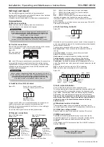
Spreaders should be used when lifting with slings to avoid damage
to the casings. Care must be taken to ensure that slings are
correctly positioned to avoid crushing and twisting of the unit
castings.
Where channels and/or support frames are bolted to the underside
of the unit casing, slings or fork-lift arms should be positioned to
locate in the apertures in the channels. If Lifting Eyes have been
supplied / fitted it is recommended that they are used.
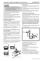
Figure 7: Lifting.
2.3 Storage
The equipment must be stored in a dry, internal location. Ductwork
connection apertures shall be sealed against the ingress of dust,
water and vermin.
Note that units that are intended for external locations are generally
not fully weatherproof until their installation, including ductwork
connections is complete.
If the storage period is to exceed two months, contact Nuaire for
guidance on the appropriate “mothballing” procedures. Do not
stack units, modules or components.
3.0 Erection and Assembly
Units must be installed in accordance with good industry practice,
upright and level on a prepared base (which may include a suitably
designed suspended platform).
Support positions should be determined to provide a distributed
support for the unit base, and should not obstruct access panels
or air way connections.
Heat recovery modules and modules that incorporate cooling coils
may produce condensation during use. An insulated drip tray and
drain connection is provided, and should be connected to a suitable
drainage point.
(*Note that provision of a powered condensate
pump is an option for this type of equipment. If such a pump is
supplied, the main drip tray drainage point should be capped,
and the pump discharge tube routed as required. Specific
instructions for the pump type fitted will be attached to the
unit.)
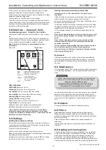
Provision may be required, and if so, should be made, for the fitting
of a correctly sized cleanable trap to each drain connection.
Figure 8: Condenste trap.
If the condensate tray is located at the inlet side of the fan (i.e.
under negative pressure) then calculate the values of
A & B as shown below. (and see fig. 5).
A = Fan inlet pressure (mm H2O) +25mm (minimum).
Allow 100mm for these units if pressure is unknown.
B = A/2. (minimum).
(Note: 10Pa = 1mm H2O).
If the condensate tray is located at the outlet side of the fan (i.e.
under positive pressure) then calculate the values of A & B as
shown below.
A = 25mm (minimum).
B = Fan outlet pressure (mm H2O) + 25mm (minimum).
Allow 100mm for these units if pressure is unknown.
The installation, including all external services and controls should
be installed in accordance with the appropriate authority and
MUST conform to all governing regulations e.g. CDM,CIBSE, IEE,
and in strict accordance with the applicable Building Regulations.
2
Assembly with base frame.
Palletised.
Forklift.
Slings via spreaders fitted to unit with
base frame.
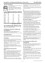
Safety first! –before commencing any work ensure:
•
That all appropriate risk assesments have been carried
out, and the required safety measures have been taken
•
That you understand the work required
•
That you are trained and competent to carry it out
08. 06. 18. Leaflet Number 671408
Hand tight plug
B
A
From
condensate
drain pan
Hand tight plug
Connect to
ventilated
downpipe
to drain


