The dampers must be installed indoors, away from
sources of heat, steam or water spray.
Operating ambient: 5-40
o
C, up to 95%RH (non condensing).
This unit must be earthed.
Do not distort the casing as this will cause the
moving part to jam.
Please note the dampers’ orientation is indicated
by the arrow. This must correspond to the direction of
the airflow when installing the damper.
5.0 Installation
The installation must be carried out by competent personnel in
accordance with the appropriate authority and conforming to all
statutory and governing regulations.
The CVD damper must be located in an accessible location for
service and maintenance as prescribed in the CDM regulation.
If the rigid ducting at the inlet and outlet of the damper are securely
fixed to their support; the damper may be coupled directly to the
ducting without additional fixing. If this is not the case; secure the
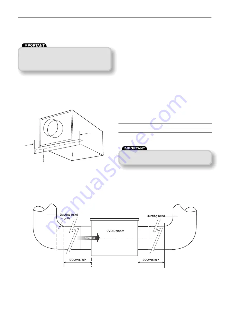
damper to a rigid, vibration-free surface using the brackets suppled
(see fig 5).
Figure 5.
Remove the screws from the underside of the unit and use these
to attach the fixing brackets.
5.1 Installation practices to obtain the
best result from the CVD damper
(see figure 6).
1.
Always fit at least 500mm of straight RIGID ducting at the
damper inlet before connecting to any bends, grilles or
obstructions (see figure 6).
2. Similarly always fit at least 300mm of straight RIGID
ducting at the damper outlet.
3. Do not fit balancing damper or other devices that creates
a jet within 10m upstream of the inlet to the CVD damper.
4. Avoid multiple bends near the inlet side of the CVD damper.
5. Avoid the use of flexible ducting; do NOT fit flexible ducting
directly on to the CVD damper. See items 1 and 2.
6. Air valves with screw-in adjustments should be set up with
maximum opening.
Failure to meet these conditions means the damper’s calibration
may be affected and would require careful commissioning to
produce the desired flowrate.
See commissioning guide on page 4.
Typical accuracy of the dampers under ideal conditions are:
Unit
Typical Accuracy
CDV 125
+ or - 3 l/s
CDV 150
+ or - 3 l/s
CDV 200
+ or - 4 l/s
Installation and Maintenance
CVD Constant Volume Dampers
Figure 6. Installation practices to obtain the best result from the CVD damper.
(Also see 5.2 Top installation tips on page 3).
2
10. 05. 17. Leaflet Number 671638
50
50


