background image


© Brüel & Kjær Vibro 

● C104958.002 / V04 ● 

Page 29 of 32 

Technical alterations reserved! 

Brüel & Kjær Vibro 

Instructions Sensor ds821 4 mm 

Declaration of conformity  

EN 


UNRESTRICTED DOCUMENT 

10 

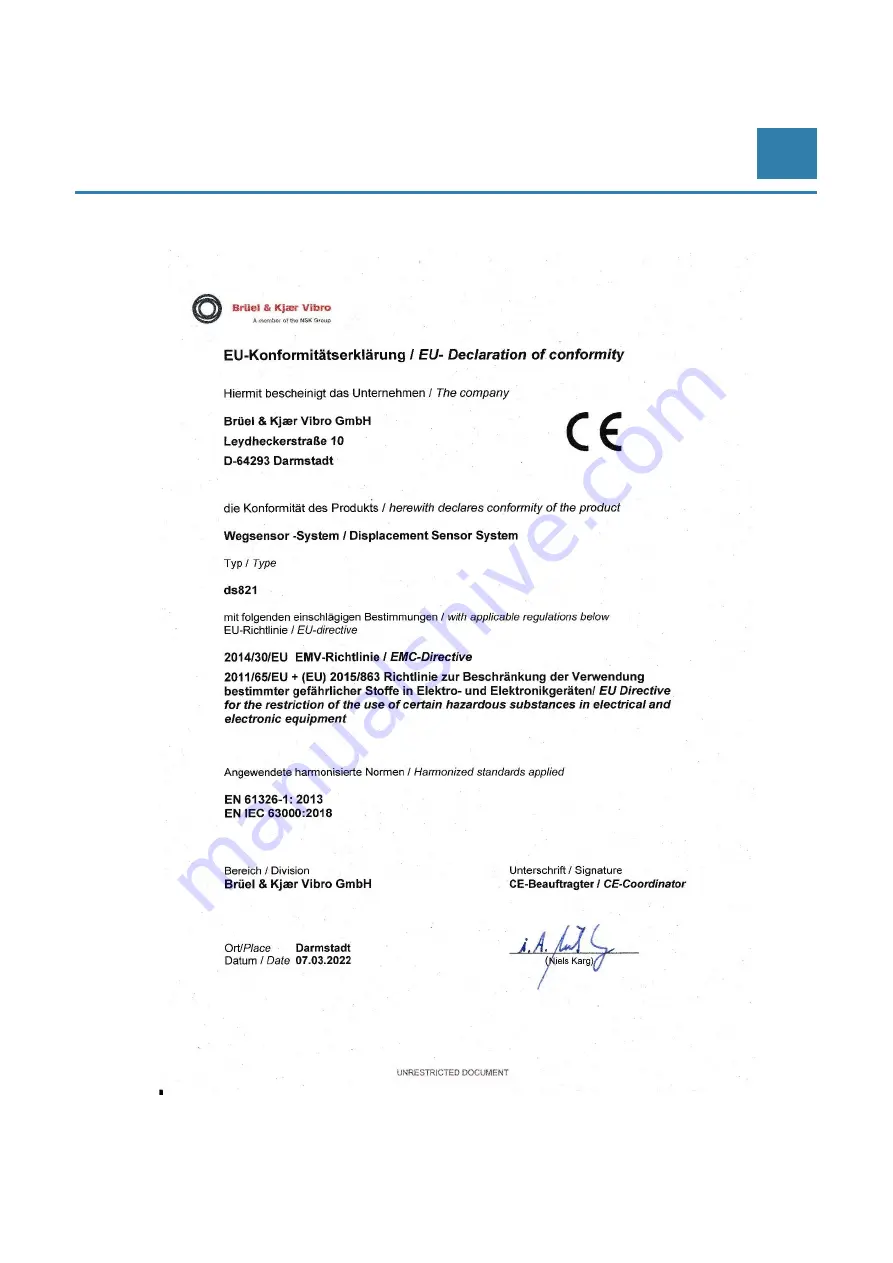
Declaration of conformity 


Summary of Contents for Bruel & Kjaer Vibro ds821 Series

Page 1: ...Keep accessible for future reference Instructions Displacement sensor system series ds821 Measuring range 4 mm ...

Page 2: ...to parts of this technical documentation Instructions Sensor ds821 4 mm C104958 002 V04 en date of issue 07 03 2022 Brüel Kjær Vibro GmbH Leydheckerstrasse 10 64293 Darmstadt Germany Phone 49 6151 428 0 Fax 49 6151 428 1000 Brüel Kjær Vibro A S Lyngby Hovedgade 94 5 sal 2800 Lyngby Denmark Phone 45 69 89 03 00 Fax 45 69 89 03 01 BK Vibro America Inc 1100 Mark Circle Gardnerville NV 89410 USA Phone...

Page 3: ...nts of the displacement sensor system 9 2 3 Nominal overall length of the displacement sensor system 10 3 Delivery storage transport 11 3 1 Delivery 11 3 2 Storage and transport 11 4 Installation 12 4 1 Assembling the displacement sensor 13 4 1 1 Displacement sensor for front side mounting 13 4 1 2 Displacement sensor for rear side mounting 14 4 2 Assembling the driver oscillator demodulator 14 4 ...

Page 4: ...echnical data 23 8 1 Non contacting displacement sensor system Series ds821 23 8 2 Dimensioning of assembly adapter 24 8 3 Environmental requirements 25 8 3 1 Reliability of the displacement sensor in different media 25 8 3 2 Properties of the measuring track 25 8 3 3 Required clearances and minimum distances for displacement sensors 26 8 4 Transfer characteristics 27 8 4 1 Characteristic curve fo...

Page 5: ...e eddy current displacement sensor system is intended solely for measuring mechanical distances and oscillations and is used primarily for the condition monitoring of slide bearings or rotating shafts The use of the measuring chain is indoors or outdoors when the driver is installed in a suitable protective housing If sensors and cables are used in a way not described in the relevant user manuals ...

Page 6: ...med by skilled expert and authorized workers for ATEX systems according to EN 60079 14 Among these works are Installation and Commissioning Installation and commissioning primarily concern work on electrical equipment These works may be performed exclusively by electricians or workers instructed and supervised by an electrician in accordance with electrotechnical regulations directives Change of S...

Page 7: ...ct the sensor tip using the supplied protective rubber cap 1 7 Information on assembly and disassembly NOTE To ensure that the displacement sensor system is functioning properly do not change the physical length of any of the system cables You must also ensure that the components used the displacement sensor and the extension cable add up to a nominal system length of 5 m 10 m or 25 m CAUTION Dang...

Page 8: ...r cap for later use To avoid damage make sure especially during assembly and while operating the machine that the sensor tip does not come into contact with other objects Loose ceramic particles can lead to damage within the machine Check the tip of the sensor for damage before every assembly Never install a defective sensor Assembly disassembly or replacement of components NOTE Never pull the cab...

Page 9: ... status of the rotating shafts as a part of surveillance of the machine 2 2 Components of the displacement sensor system The eddy current displacement sensor system consists of the components of displacement sensor with an integrated cable an optional separate extension cable and the driver oscillator demodulator The name of a component is a combination of the series name ds821 and the component d...

Page 10: ... help of the additional extension cable must be extended to the nominal system length of 5 m 10 m or 25 m If the displacement sensor already has the nominal system length no additional extension cable is required In this case the displacement sensor system consists only of the components displacement sensor and driver Example correct installation for a nominal length N of 5 m P 0 5 m L 4 5 m P L 5...

Page 11: ...X X X X Measurement protocol works calibration X Instruction X X X X Table 3 1 Components included in scope of supply 3 2 Storage and transport We recommend storing the system in its original packaging The following conditions must be observed Stacking height max 6 packages Storage temperature 20 C to 70 C Humidity max 75 Packaging dimensions Displacement sensor system complete max 3 parts Interna...

Page 12: ...required clearances and the width of the measuring track are considered 8 3 2 Properties of the measuring track und 8 3 3 Required clearances and minimum distances for displacement sensors Required clearances and minimum distances for displacement sensors The sensitivity of the target material is known Recommended accessories for trouble free operation Install the driver in a housing control cabin...

Page 13: ...he help of a suitable sensor holder The sensor holder must be mounted in a position where it cannot move relative to the object to be measured during machine operation 1 Remove the protective cap from the sensor tip 2 Attach the displacement sensor using a sensor holder suitable for the chosen type of assembly 3 Position the sensor so that it lies vertically to the measuring track 4 To avoid damag...

Page 14: ... on a firm surface 4 2 1 Mounting on hat rail For mounting on a hat rail the mounting tabs for screw mounting can be separated at the predetermined breaking point 1 For screw mounting break off both tabs and attach the driver with the assembly adapter by sliding it into place figure 2 Affix the assembly adapter to a hat rail DIN EN 60715 TH35 Place rear part of the assembly adapter see figure abov...

Page 15: ...ad 12 mm Steel 2 sheet metal screws A2 2 washers A2 inner diameter 4 5 mm Steel thickness 1 2 1 4 mm Core hole diameter 3 3 mm Aluminium 2 sheet metal screws A2 2 washers A2 inner diameter 4 5 mm Aluminium thickness 1 2 1 4 mm Core hole diameter 3 4 mm 1 Mark the positions for both drill holes section 8 2 Dimensioning of assembly adapter 2 Drill two mounting holes 3 Connect the assembly adapter wi...

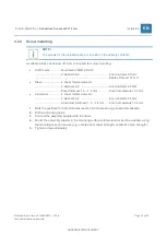
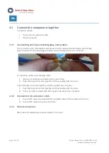
Page 16: ...ble observe the following order 1 Hold one of both plug connector ends in each hand 2 Push both plug connectors together until they audibly click into place Push both plug connectors together until they audibly click into place 1 Push both plug connectors together until they audibly click into place 2 Pull on the silver serrated part of the plug to disconnect the connection 4 3 2 Connection via ex...

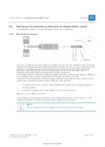
Page 17: ...scribed minimum separation to the shaft maximum displacement must be maintained The minimum distance to the target must be selected so that even in the event of maximum deflection of the shaft the distance axial or relative to the shaft does not fall below 0 5 mm In case of an axial measurement the axial bearing clearance design and the current position of the shaft must be considered in order to ...

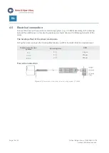
Page 18: ...en setting up your measuring system you should observe the following behavior of the driver The heating effect of the driver electronics During the warm up phase the heating effect causes a drift in the static distance measurement Displacement sensor system Operating time Drift 5 m 1 h 6 μm 10 m 1 h 12 μm 25 m 1 h 24 μm Four wire connection Figure 4 1 Connection of the driver to a monitoring syste...

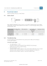
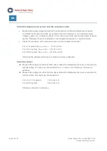
Page 19: ...tance of the electronic diagnostic system RL Operating current IB 5 m 10 m 24 VDC 2 18 V DC 100 kΩ 8 9 mA 1 mA 25 m 24 VDC 2 18 V DC 100 kΩ 8 0 mA 1 mA 5 2 Troubleshooting If you the readings you receive deviate from these proceed in accordance with the following recommended sequence Check the output signal The output signal USIG 18 V The distance between target and sensor tip lies outside the mea...

Page 20: ...resistance of the extension cable and the displacement sensor For a 5 m system Rsensor Rext 8 7 Ω 0 5 Ω For a 10 m system Rsensor Rext 12 1 Ω 0 5 Ω For a 25 m system Rsensor Rext 26 6 Ω 2 0 Ω Otherwise the displacement sensor or extension cable is defective Check the driver Measure the voltage terminal 2 at the driver without the displacement sensor connected and without cables The result you shou...

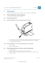
Page 21: ...ith assembly adapter on hat rail 1 Use a screwdriver to pull the tab forward and vertically lift off the adapter containing the driver 2 To remove the assembly adapter push the adapter s tappet opposite of mounting tab downward and slide off the driver 6 2 2 Disassembling driver with assembly adapter screw mounted 1 Remove screws 2 Remove assembly adapter 6 3 Replacing displacement sensor system c...

Page 22: ...cal alterations reserved EN 7 Disposal The driver is subject to the Waste Disposal Act for Electrical and Electronic Equipment Do not dispose of the device in the regular household waste and observe local waste disposal regulations WEEE Reg No DE 69572330 ...

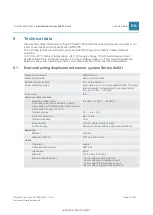
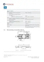
Page 23: ...ing dimension Displacement Measuring principle Eddy current process Nominal system lengths 5 m 10 m and 25 m Linear measuring range 4 mm approx 0 5 4 5 mm separation from the object to be measured corresponding to an output signal from ca 2 VDC 18 VDC Colour code red Electrical characteristics Operating voltage UB The sensor must be connected to a SELV power supply with limited power that is secur...

Page 24: ...perature Operating temperature range sensor and cable Operating temperature range driver 55 C 180 C 55 C 85 C Storage temperature2b 20 C 70 C Altitude 2000 m Polution degree 3 used in the protection of the connections and cable clamps Humidity 98 non condensing with protection of the plug connections and cable clamp 8 2 Dimensioning of assembly adapter Figure 8 1 Dimensional drawing of assembly ad...

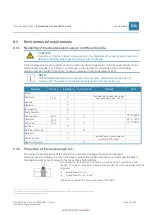
Page 25: ...sistant not resistant Remark Test Water X Salt water 7 5 X Suitable to a limited extent for the use of sea water steel 1 4301 Hexane X Heptane X Isopropanol X Soap Solution X Sulfuric acid 20 X 70 C 240 h Ammonia 32 X 25 C 150 h Nitric acid 15 X 70 C 240 h Acetone X Methylen Chloride Xa Methanol X Salt spray test X Tested 28 days for conformance with DIN EN ISO 9227 Hydrochloric acid X 8 3 2 Prope...

Page 26: ... non contacting displacement sensors strictly observe the clearances and minimum distances illustrated in the following drawing NOTE If these clearances and minimum distances must be lowered for design purposes please contact Brüel Kjær Vibro Sensor tip extending Distance to the shaft shoulder sensor parallel to electrically conductive material Sensor tip flush Required minimum diameter of the sha...

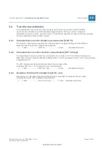
Page 27: ...escribes the interdependence of signal voltage and the distance between sensor tip and the object to be measured Y axis GAP V X axis Displacement mm 8 4 2 Characteristic curve for vibration measurement ISF mV μm The displacement sensor system has a sensitivity of 4 mV μm 101 5 mV mil with reference to B K Vibro reference material 42CrMo4 Material No 1 7225 according to DIN 17 200 corresponding to ...

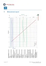
Page 28: ...Page 28 of 32 Brüel Kjær Vibro C104958 002 V04 Technical alterations reserved EN 9 Measurement report ...

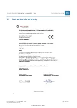
Page 29: ...rüel Kjær Vibro C104958 002 V04 Page 29 of 32 Technical alterations reserved Brüel Kjær Vibro Instructions Sensor ds821 4 mm Declaration of conformity EN UNRESTRICTED DOCUMENT 10 Declaration of conformity ...

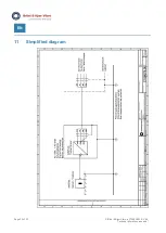
Page 30: ...Page 30 of 32 Brüel Kjær Vibro C104958 002 V04 Technical alterations reserved EN 11 Simplified diagram ...

Page 31: ... Brüel Kjær Vibro C104958 002 V04 Page 31 of 32 Technical alterations reserved Brüel Kjær Vibro Instructions Sensor ds821 4 mm Simplified diagram EN UNRESTRICTED DOCUMENT ...

Page 32: ...Vibro A S Lyngby Hovedgade 94 5 sal 2800 Lyngby Denmark Phone 45 69 89 03 00 Fax 45 69 89 03 01 BK Vibro America Inc 1100 Mark Circle Gardnerville NV 89410 USA Phone 1 775 552 3110 Corporate E Mail info bkvibro com Homepage www bkvibro com Sensor ds821 4 mm Brüel Kjær Vibro 03 2022 C104958 002 V04 Technical alterations reserved ...

Reviews: