www.nationalrailwaysupply.com 1-800-357-3572
8
38542D
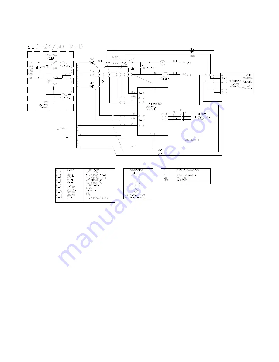
14. WIRING DIAGRAM
Page 1: ...ial which may cause burns Do not get in eyes on skin or clothing If the gelled or liquid content of the batteries contacts the skin or clothing wash the area thoroughly with water In the case of contact with the eyes flush immediately with clean water for 15 minutes and obtain medical attention e Connect or disconnect the battery plug only when the charger output is off to prevent arcing or burnin...
Page 2: ... is not being used or the temperature probe is working improperly Temperature compensation uses a temperature reference of 77 F 25 C a voltage reference of 2 23 volts the voltage of a standard gel cell battery at 77 F and a compensation value of 3 0 mV per F or 5 4 mV per C The equivalent equation for the compensated voltage is Vcomp V k t 77 F Where V is the voltage of the battery at 77 F t is th...
Page 3: ...g flanges are configured for an EIA 19 483mm rack for a forward mounting arrangement note the width from the outer edge fo one mounting flange to the outer edge of the other mounting flange is 19 15 16 Fasteners to match the thread of the rack should be used in all 7 rack mounting horizontal slots on each of the 2 mounting flanges 14 rack mounting slots total to maximize the mounting integrity The...
Page 4: ... CAPACITOR 7 TEMPERATURE PROBE The external temperature probe is an optional way of extending battery life by using temperature compensation One end of the temperature probe cable has a three pin plug which plugs into a receptacle labeled TEMP PROBE on the front of the charger The other end of the cable has the temperature sensor sealed either in a terminal or small metal box WARNING IT IS IMPORTA...
Page 5: ...inch maximum blade width is required to insert or remove a wire from a relay terminal WARNING BE CAREFUL IF AN UNINSULATED METAL TOOL CONTACTS BOTH THE GROUNDED CHARGER CASE AND A RELAY TERMINAL PUSH IN TAB THIS WILL CAUSE A POTENTIALLY DAMAGING AND OR DANGEROUS ELECTRICAL SHORT Current Monitor Alarm Operation Table 9 1 outlines the operation of the LED and relay based on the status of the current...
Page 6: ...turns on and the CLOSED relay contact closes Turn the current limit adjustment approximately 1 8 of a turn counterclockwise from this switching point Remove AC power from the charger to verify that the current monitor alarm is functioning The LED should turn off and the CLOSED relay contact should open Current Monitor Specifications CURRENT MONITOR ALARM RELAY CONTACT RATINGS 1A at 30 Vdc 0 5A at ...
Page 7: ...5 38309S 1 CURRENT MONITOR MODULE W ELECTRONIC BOARD 27545 01 38308S 1 CURRENT MONITOR MODULE MOUNT 38811S 1 CONTROL CABLE CURRENT MONITOR 05322S 2 FUSEHOLDER ASSEMBLY 15029S 2 FUSE 12 AMP 38888S 1 CIRCUIT BREAKER ASSEMBLY 31457S 1 AC SWITCH ASSEMBLY 27319S 1 AMMETER 50 AMP 14197S 4 BUSHING 1 29741S 1 TEMPERATURE TRANSDUCER 10 W TERMINAL 29742S 1 TEMPERATURE TRANSDUCER 30 W TERMINAL 14742S 1 HEATS...
Page 8: ...www nationalrailwaysupply com 1 800 357 3572 8 38542D 14 WIRING DIAGRAM ...