Version 0.2
20
SCS-1002
Operating manual
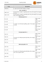
Figure 7 – Exterior of SCS-WP
Table 9 – Controls and LEDs of SCS-WP
Pos.
Name
Description
1
Brightness
knob
To adjust brightness of controls
2
Reset
button
To provide temporary mute of sound signaling
3
Speaker
To provide sound call signaling
4
Power
LED
To display power supply status
5
Fault
LED
To display faults
6
Call
LED
To display a call
2.1.4
Repeater SCS-CU-REP
SCS-CU-REP
provides call signaling on a standby watch station when a call signal
from a controller occurs in the data exchange network.
The unit is recommended for additional control of calls from call buttons and (or)
work of RCD operator. The unit functions as RCD repeater with an option to mute local
sound call signaling.
Note – The unit may be used as a repeater of RCD in repeater mode.
The unit has the same functionality and outfitted with the same controls and LEDs
as SCS-CU, except power on button (for connected units).
2.2
C
ONTROLLERS OF CALL BUTTONS
Controllers of call buttons are designed to detect a call from a call button and to
transmit it to RCD via RS-485 network.

