background image


OPERATING INSTRUCTIONS AND 

SYSTEM DESCRIPTION FOR THE 
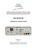
ISO-STIM 01B 


STIMULUS ISOLATOR 


VERSION 1.8 

npi 2016 


npi electronic GmbH, Bauhofring 16, D-71732 Tamm, Germany 

Phone +49 (0)7141-9730230; Fax: +49 (0)7141-9730240 

[email protected]; http://www.npielectronic.com 

Summary of Contents for ISO-STIM 01B

Page 1: ...STEM DESCRIPTION FOR THE ISO STIM 01B STIMULUS ISOLATOR VERSION 1 8 npi 2016 npi electronic GmbH Bauhofring 16 D 71732 Tamm Germany Phone 49 0 7141 9730230 Fax 49 0 7141 9730240 support npielectronic com http www npielectronic com ...

Page 2: ...e for High Voltage Instruments 4 3 ISO STIM 01 B 5 3 1 System Description 5 3 2 Description of the Front Panel 5 3 3 Description of the Rear Panel 8 3 4 ISO CAB optional accessory 8 3 5 Operation 9 3 5 1 Connections Noise Reduction 9 3 5 2 Operation Modes 9 4 Power Supply 10 5 Technical Data ISO STIM 01B 11 ...

Page 3: ...ge before connecting any system to mains Always use a three wire line cord and a mains power plug with a protection contact connected to ground protective earth Before opening the cabinet unplug the instrument Unplug the instrument when replacing the fuse or changing line voltage Replace fuse only with an appropriate specified type 3 STATIC ELECTRICITY Electronic equipment is sensitive to static d...

Page 4: ...er supplies to protective earth 2 Do not touch connections unless the instrument is turned off and the capacitance of both the load and power supply are earthed 3 Allow adequate time for discharge of internal capacitance of the power supply 4 Do not ground yourself or work under wet or damp conditions 5 Servicing should be only done by qualified personnel aware of the hazards 6 If in doubt return ...

Page 5: ...T INPUT allows the pulse length to be externally controlled whereas amplitude and polarity are controlled by the device itself For both timing modes the generated pulses can be unipolar or bipolar In bipolar mode an interphase gap IPG of adjustable length can be inserted between the two pulses 3 2 Description of the Front Panel Figure 1 Front panel view of ISO STIM 01B In the following description...

Page 6: ...MODE the limit 100 V is set by the corresponding voltage at the electrode due to Ohm s Law V I R i e this control indicates during an experiment in CURRENT OUTPUT MODE that the electrode resistance increases and the amplifier is not be able to provide the current which is set if the electrode resistance increases further 8 STIM LED LED indicating the application of a voltage or current stimulus 9 ...

Page 7: ...nge to be set with the AMPLITUDE potentiometer 5 16 IPG TIME µs potentiometer with switch Potentiometer to select the interphase gap time IPG in bipolar stimulation mode see 3 5 2 IPG is turned off in the leftmost position switch 17 DIRECT INPUT TTL BNC connector A TTL signal can be fed in here to trigger the output of the ISO STIM 01D Amplitude will be set by 5 6 15 In unipolar mode 4 the output ...

Page 8: ...ector are connected to the ISOLATED OUTPUT connectors on the front panel of the ISO STIM 01 D Each of these stimulation lines has a shield which is connected to the common green SHIELD connector To reduce noise during recordings this connector can be connected to the CHASSIS connector at the ISO STIM 01 D front panel The other end of the cable provides open wires to which different connector types...

Page 9: ...ed the whole slice will be stimulated resulting in a DC shift of the whole slice 3 5 2 Operation Modes BIPOLAR The isolator is capable to generate biphasic stimuli by switching the stimulus mode switch to BIPOLAR ON In this mode the stimulus that is set by the user will be followed by a second stimulus with the same amplitude and duration but with reverse polarity There is no delay between first a...

Page 10: ...left and rear panel right view of the ISO STIM 01B power supply The power supply is connected to mains with a standard power cord It has a POWER ON switch on the rear panel Important Only use the supplied power supply to power the ISO STIM 01B Using different power supplies might result in damage of ISO STIM 01B and or power supply Important This power supply is designed for use with the ISO STIM ...

Page 11: ...bipolar selected by toggle switch Output voltage 100 V max isolated Output current 10 mA max isolated IPG interphase gap 50 500 µs Power requirements 100 240 V AC only use supplied power supply Fuses Power Supply 1 25 A slow Dimensions ISO STIM 01B 246 x 188 x 89 mm W x D x H Power Supply 103 x 169 x 59 mm W x D x H ...

Reviews: