


AUD-08 B User Manual
_______________________________________________________________________________________________________________
___________________________________________________________________________
version 1.1
page 6
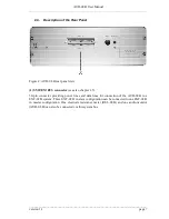
(6)
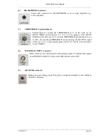
HEADPHONES connector
Stereo jack connector for HEADPHONES or an external amplifier (e.g.
active speakers).
(7)
THRESHOLD % potentiometer
Potentiometer for setting the THRESHOLD in % of the value set by
INPUT MODE switch #4 (0.5 V, 1 V, 2 V). For example, if the INPUT
MODE switch #4 is set to 2 V and the THRESHOLD potentiometer is set
to 80%, the resulting THRESHOLD for monitoring the OUTPUT signal
will be at 1.6 V, i.e. only signals greater than 1.6 V will be converted into a
sound (NOISE).
(8)
EXTERNAL INPUT connector
BNC connector for connecting the external input signal. To monitor this signal,
the CHANNEL SELECT rotary switch (#3) must be set to EXT.
(9)
GROUND connector
Banana plug providing ground. The plug is connected internally to the shields of
the BNC connectors.


