background image

NVR-6332-H8


User’s manual (Short) ver.1.0


All rights reserved © AAT Holding S.A. 


STARTING THE DEVICE 

2.2 HDD 

mounting


Novus  NVR-6332-H8 supports up to 8 internal SATA HDDs. 

WARNING! 
In  order  to  find  information  regarding  the  compatible  models  of  HDDs  and  their  maximum 
capacities,  please  contact  Novus  distributor  or  check  the  information  presented  at  
www.novuscctv.com. AAT HOLDING Company is not responsible for any problems from using 
not recommended hard drives. 

The list of compatible HDDs contains all the HDDs that can be used with a given DVR including 
HDDs designed for office use - so called desktop disks. However, due to the fact that reliability of 
the recording process and data safety are paramount factors of any CCTV system, we strongly 
advise to use HDDs designed for continuous (24/7) operation. 

You need to format disks if they were used in a different device. All data saved on HDD prior to 
format will be lost. 


HDDs Installation 


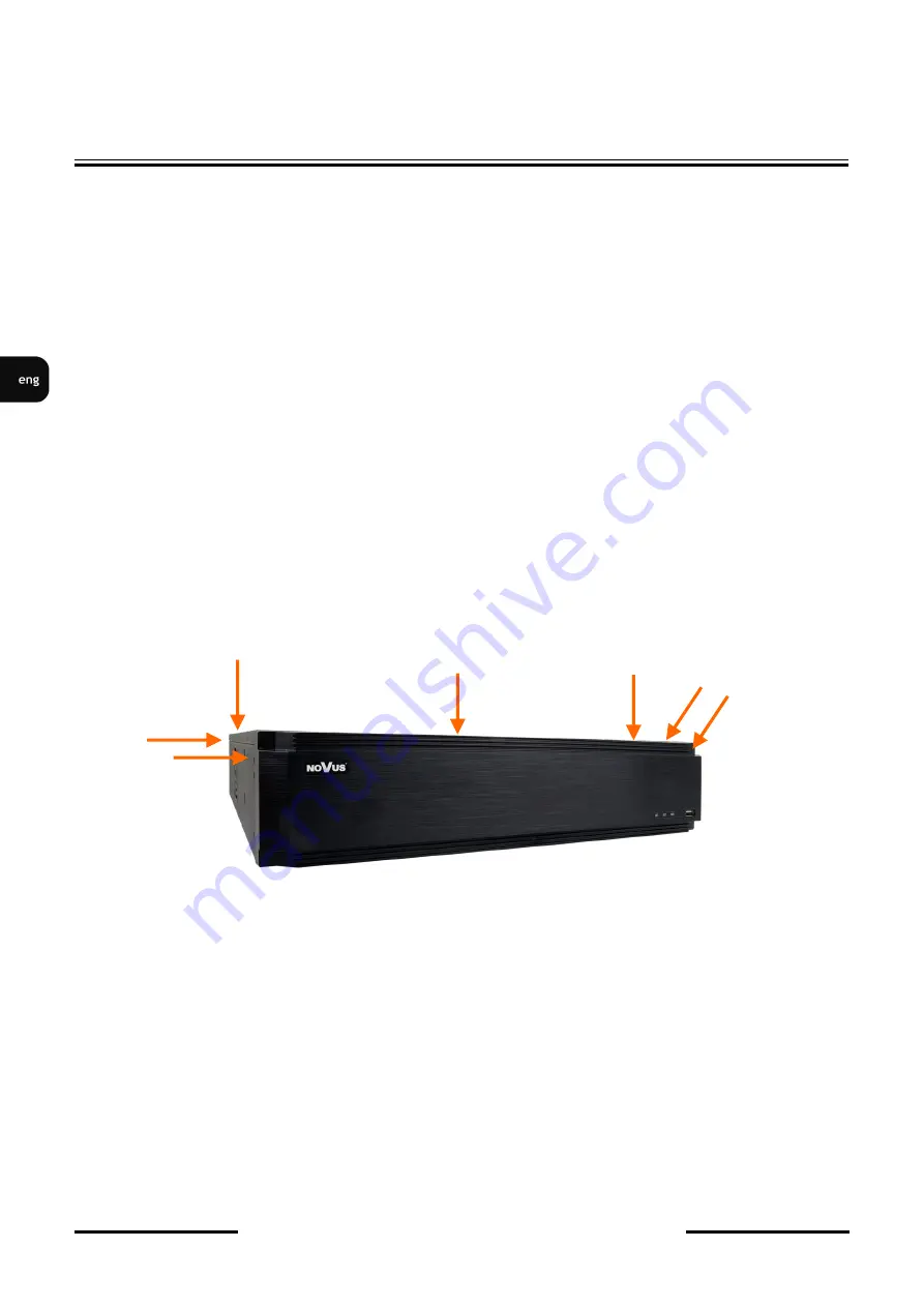
To install the hard disks, unscrew 3 screws on the back of the casing and two on the each side of the 
recorder casing (pointed by arrows), sliding top cover backwards and then lifting it up. 


WARNING:  ! 

Before removing cover unplug the power cord from the NVR. When NVR is turned on before 
disconnecting the power cord, shut down the recorder using the NVR menu.  
If you use the disk previously  used in another device, it is necessary to format it before using. 
Formatting the drive erase all the data from disk. All drives in the recorder should be exactly the 
same type. 


Summary of Contents for NVR-6332-H8

Page 1: ...User s manual short NVR 6332 H8 ...

Page 2: ...f the device in the system ATTENTION PRIOR TO UNDERTAKING ANY ACTION THAT IS NOT PROVISIONED FOR THE GIVEN PRODUCT IN ITS USER S MANUAL AND OTHER DOCUMENTS DELIVERED WITH THE PRODUCT OR THAT ARISES FROM THE NORMAL APPLICATION OF THE PRODUCT ITS MANUFACTURER MUST BE CONTACTED OR THE RESPONSIBILITY OF THE MANUFACTURER FOR THE RESULTS OF SUCH AN ACTION SHELL BE EXCLUDED 1 Prior to undertaking any act...

Page 3: ...5 6 TB SATAEdit feature Total Capacity 48 TBEdit feature ALARM Internal Alarm Input Output 8 4 relay typeEdit feature Camera Alarm Input Output supports camera s alarm input output Edit feature Motion Detection supports camera s motion detection Edit feature System Reaction to Alarm Events buzzer e mail alarm output activation recording activation PTZEdit feature NETWORK Network Interface 2 x Ethe...

Page 4: ...rers may vary by some functions which can make them work improperly or not in accordance with expectation AAT HOLDING Company is not responsible for incompatibility problems resulting from cameras of other brands than NOVUS which are using ONVIF protocol If you are using ONVIF protocol cameras other than NOVUS brand it is recommended to test each time whether required functions work correctly 1 3 ...

Page 5: ...or 4 USB USB port for external Flash memory and other USB devices 5 HDMI HDMI connector use the HDMI cable to connect monitor 6 CONNECTORS Block of alarm input output connectors 7 AUDIO IN Audio mono inputs to connect microphones 8 FAN Air outlet of the power supply do not cover 9 POWER SWITCH Power switch 10 POWER SOCKET To plug in the 230 V power cord 11 E SATA Sockets for connecting E SATA devi...

Page 6: ...ity of the recording process and data safety are paramount factors of any CCTV system we strongly advise to use HDDs designed for continuous 24 7 operation You need to format disks if they were used in a different device All data saved on HDD prior to format will be lost HDDs Installation To install the hard disks unscrew 3 screws on the back of the casing and two on the each side of the recorder ...

Page 7: ...t mount the racks inside the DVR and connect power signal cables After connecting disks please put the top cover onto the DVR and turn the device on in order to check the operation of particular components and to format the HDDs CAUTION If the device was brought from a location with lower temperature please wait until it reaches the temperature of location it is currently in Turning the device on ...

Page 8: ...s is prohibited To shut down the device please use the menu CAUTION Make connection when the power is not applied and the power switch is turned off Do not place the power cord under the carpet or rug The power cord is usually earth grounded However even if it s not earth grounded never modify it on your own for earth grounding Make sure that power adapter is placed near of NVR and secured from ac...

Page 9: ...k cameras from NVR access network The second mode called NETORK FAULT TOLERNANCE allows one of network sockets of the recorder to be used as an active fault tolerant connection in case if the main of main connections fails The permissible cable distance from the switch to each camera is 100m Cameras Internet and other devices should be connected as shown below We recommend that you configure the c...

Page 10: ...eras according to the instructions of the camera 2 7 Connecting external devices Connecting audio ports Audio output signal normally are above 200mV 1kΩ load You can connect to it the audio amplifier with the external speakers Connecting USB devices NVR has 1 x USB 2 0 port on front and one 1 x USB 2 0 and 1 x 3 0 USB port on back panel They could be used for connecting external Flash memory mouse...

Page 11: ...ed AAT Holding S A 11 Connecting alarms ports Example of connecting alarm output no 1 follow the drawing below Example of sensor connection to alarm input 1 STARTING THE DEVICE NO COM ALARM Power source NO1 COM1 ALARM Power source GND Alarm in Alarm out RS485 ...

Page 12: ...lit screen display mode switches the display to full screen mode Subsequent double click returns to previous display mode Move cursor to the top or click the right key of mouse to bring up MAIN MENU and select START icon Certain positions allow to select them via mouse scroll Depending on NVR operating mode pressing RMB displays a corresponding function menu 3 3 System menu operations To start NVR...

Page 13: ...T Holding S A 13 To unlock the DVR menu click the button at the bottom left of the screen After clicking on button click on LOGIN Then login in entering password in PASSWORD field default password for user root is pass and then click in LOGIN button NVR OPERATING ...

Page 14: ...ase refer to the Cameras Capability Table available on the www novuscctv com website If you set wrong values some problems may appear the NVR cannot search the IP camera the stream cannot be connected the image is not fluent the image quality is bad and so on In case of first NVR start WIZARD SETUP menu window will occur if function wasn t disabled earlier To configure NVR please follow procedure ...

Page 15: ...s for switch in INTERNAL ETHERNET PORT SECTION Please note that IP subnet for the ETHERNET PORT 1 and INTERNAL ETHERNET PORT were different In cases where it is necessary to connect NVR to the Internet for remote access email sending etc configure the following parameters Gateway Primary and Secondary DNS You can also enable DHCP mode which allows you to download an IP address from a DHCP server r...

Page 16: ...e connected to the Internet network behind a router equipped with NAT NOTE AAT Holding S A is not responsible for the operation of the service autonat com which is provided by third parties III Add Camera Allows you to configure the camera and add them to the recorder Upper window displays cameras discovered by the NVR To change the addressable cameras click on the icon in the column EDIT This wor...

Page 17: ...ra will be displayed on the bottom of the menu list To edit the connection settings of the camera press the EDIT column If you are having problems connecting to the camera you must enter the correct user name in the USER NAME and password in the PASSWORD field and then press the OK button to save the settings If the NVR connected to the camera in STATUS filed will be displayed Connected To remove ...

Page 18: ...mat the hard disk by selecting it in the list of drives and then pressing FORMAT Formatting may take a few moments After properly formatted STATUS field should have a value of RW Read Write V Record Settings You can set one of the modes MANUAL RECORD SETTINGS You can set the recording time from the moment you select the manual recording in range from 1 minute to 1 hour or manually off recording NV...

Page 19: ... MOTION RECORD continuous recording and recording after receiving motion detection information from the camera ALWAYS 24x7 RECORD SENSOR RECORD continuous recording and recording alarm generated on alarm input ALWAYS 24x7 RECORD MOTION RECORD SENSOR RECORD continuous recording and recording alarm generated on alarm input and after receiving motion detection information from the camera ALWAYS 24x7 ...

Page 20: ...ation process it will enter the real time monitoring image Displaying all cameras simultaneously is the default mode On the bottom of screen STATUS BAR is displayed To start access to the NVR click on the button to launch the start menu After clicking log on to the system the default password for the root user is a pass STATUS BAR description NVR MENU Item Icon Description Search Launches search f...

Page 21: ...m Icon Description Settings Click to open start menu Full screen Switches video view to full screen Single view Start displaying camera in single view Quad view Start displaying 4 cameras in video view 9 cam View Start displaying 9 cameras in video view Other divisions Opening video subdivisions Other divisions Open 1 main 5 7 or 12 additional views Dwell Starts displaying images in sequence Dwell...

Page 22: ...on off manually recording channels Manual Alarm Allow to trigger the alarm manually Recording Status Displays information about the recording Alarm Status Displays the status of alarm devices Disk Status Information about disk status Network status View information about network usage Device Information Displays information about the state of operation of the basic components of recorder Item Icon...

Page 23: ...a saved by manual recording Blue Schedule continuous data recording Yellow Motion motion event data recording Red Alarm alarm event data recording To play the searched data simply double click a desired point on or press PLAY button To control playback you can use the following buttons from the playback options Stop stops replaying Rewind Starts playback backward using key frames Pause Play Stop P...

Page 24: ...ion registered for the selected channel Backup start menu archiving recordings Backup status displays the current status of archival recordings Back close the replay menu 4 3 Changing the menu language If after NVR booting up the currently selected menu language is different than expected to change it please follow the steps below Click on bottom left on start menu button Then select menu options ...

Page 25: ...r 1 0 All rights reserved AAT Holding S A 25 In the displayed menu select the English language in the third box from the top and click the button on the bottom menu After saving settings the language will be switched to English NVR MENU ...

Page 26: ...2017 05 31 MB MK AAT Holding S A 431 Pulawska St 02 801 Warsaw Poland tel 4822 546 07 00 fax 4822 546 07 59 www novuscctv com ...

Page 27: ...instrukcja obsługi skrócona NVR 6332 H8 ...

Page 28: ...WALIFIKOWANYCH PRACOWNIKÓW SERWISU 1 Przed zainstalowaniem i rozpoczęciem eksploatacji należy dokładnie zapoznać się z niniejszą instrukcją obsługi i zawartymi w niej wymogami bezpieczeństwa 2 Uprasza się o zachowanie instrukcji na czas eksploatacji rejestratora na wypadek konieczności odniesienia się do zawartych w niej treści 3 Należy skrupulatnie przestrzegać wymogów bezpieczeństwa opisanych w ...

Page 29: ...u 8 x HDD 3 5 6 TB SATA Edytuj cechę Maksymalana łączna pojemność 48 TBEdytuj cechę ALARMY Wejścia wyjścia alarmowe lokalne 8 4 typu przekaźnikEdytuj cechę Wejścia wyjścia alarmowe w kamerach wsparcie wejść wyjść dostępnych w kamerach Edytuj cechę Detekcja ruchu wsparcie detekcji ruchu dostępnej w kamerach Edytuj cechę Reakcja na zdarzenia alarmowe sygnał dźwiękowy e mail aktywacja wyjścia alarmow...

Page 30: ...poszczególne funkcje mogą działać niepoprawnie lub niezgodnie z oczekiwaniem Firma AAT HOLDING S A nie ponosi odpowiedzialności za problemy wynikłe z niekompatybilności kamer innych marek niż NOVUS podłączanych przy wykorzystaniu protokołu ONVIF W wypadku korzystania z protokołu ONVIF w kamerze marki innej niż NOVUS zaleca się każdorazowo przeprowadzić test na poprawność obsługi w rejestratorze po...

Page 31: ... innych kompatybilnych urządzeń 5 HDMI1 Złącze monitora spot w standardzie HDMI 6 ZŁĄCZA Blok złączy wejść wyjść alarmowych 7 AUDIO IN Wejście audio do podłączenia mikrofonu 8 WENTYLATOR Wylot powietrza zasilacza nie należy zasłaniać 9 WŁĄCZNIK Włącznik zasilania 230 V AC 10 GIAZDO 230V Gniazdo do połączenia przewód zasilania 230 V 11 E SATA Gniazda do podłączenia urządzeń E SATA 12 AUDIO OUT Wyjś...

Page 32: ...riorytetem jest niezawodność procesu rejestracji i zarządzania danymi zaleca się stosowanie dysków przeznaczonych do pracy ciągłej tzw 24x7 Jeżeli użyty dysk był stosowany w innym urządzeniu konieczne jest jego formatowanie Należy mieć to na uwadze ze względu na utratę danych Opis instalacji dysków W celu zamontowania dysków twardych należy po odkręceniu trzech śrub z tyłu obudowy i po dwóch z każ...

Page 33: ... dołączonych do rejestratora Następnie należy zamontować listwę z dyskami w rejestratorze i podłączyć przewody zasilające oraz sygnałowe Po podłączeniu dysków twardych należy zamknąć obudowę rejestratora i uruchomić go w celu sprawdzenia poprawności połączeń oraz sformatowania dysków twardych UWAGA Jeżeli urządzenie przyniesione zostało z otoczenia o niskiej temperaturze należy odczekać aż osiągni...

Page 34: ...0 sekund W tym czasie nie należy uruchamiać żadnych funkcji urządzenia i naciskać żadnych przycisków Wyłączenie urządzenia odbywa się z poziomu menu UWAGA W czasie podłączania przewodu zasilającego włącznik zasilania powinien być wyłączony Nie należy modyfikować podłączenia zasilaczy i ich uziemienia W celu zapewnienia nieprzerwanej pracy urządzenia należy upewnić się ze wszystkie połączenia wykon...

Page 35: ...ię kamery od sieci dostępu do NVRa Drugi tryb nazywany TOLERANACJA BŁĘDÓW umożliwia wykorzystanie jednego z gniazd sieciowych rejestratora jako zapieczenia połączenia w przypadku utraty głównego połączenia sieciowego Dopuszczalna odległość kabla od przełącznika sieciowego do każdej z kamer wynosi 100m Kamery Internet i inne urządzenia należy podłączyć jak pokazano poniżej Zalecamy skonfigurowanie ...

Page 36: ...m i nieautoryzowanym dostępem zalecamy wydzielenie sieci kamer od sieci dostępu do NVRa 2 7 Połączenia urządzeń zewnętrznych Podłączanie audio Wyjście audio umożliwia podłączenia głośnika ze wzmacniaczem Sygnał na wyjściu audio wynosi ok 200mV przy impedancji obciążenia 1kΩ Podłączenie urządzeń USB Rejestrator posiada 1 port USB 2 0 na panelu przednim i tylnym oraz 1 port USB 3 0 na panelu tylnym ...

Page 37: ...jść i wyjść alarmowych Przykład podłączenia wyjścia alarmowego nr 1 należy wykonać zgodnie z rysunkiem przedstawionym poniżej Przykład podłączenia czujnika do wejścia alarmowego nr 1 URUCHAMIANIE URZĄDZENIA NO1 COM1 ALARM Źródło zasilania ALARM CZUJNIK Złącza masy Wejścia alarmowe Wyjścia alarmowe Złącza RS485 ...

Page 38: ...ej pełnoekranowo Ponowne podwójne kliknięcie wskaźnikiem myszy powoduje powrót do poprzedniego formatu wyświetlania W czasie konfiguracji wyboru poszczególnych pozycji dokonuje się przy użyciu lewego przycisku myszy W wybranych pozycjach zmiany wartości danego pola można dokonać przy użyciu rolki myszy Zależnie od aktualnie wybranego menu wciśnięcie prawego przycisku myszy wywołuje odpowiednie men...

Page 39: ...ora należy kliknąć na przycisk w lewej dolnej części ekranu wskażnik strzałki Po kliknięciu w wyświetlonym menu należy kliknąć na pozycję LOGOWANIE Następnie w oknie logowania należy wpisać hasło w polu HASŁO Domyślne hasło dla użytkownika root to pass a następnie kliknąć na przycisk logowania LOGOWANIE OBSŁUGA REJESTRATORA ...

Page 40: ...ą się w Tabeli kompatybilności kamer dostępnej na stronie www novuscctv com W przypadku ustawienia niewłaściwych wartości mogą wystąpić problemy z wyszukaniem podłączeniem kamer lub uzyskaniem płynnego obrazu bez zniekształceń Przed przystąpieniem do pracy z rejestratorem sieciowym należy przeprowadzić wstępną konfigurację urządzenia Należy kliknąć na przycisku KREATOR USTAWIEŃ w celu uruchomienia...

Page 41: ...DRES IP domyślne 192 168 1 100 MASKA PODSIECI domyślne ustawienia to 255 255 255 0 W rejestratorze możliwe jest zaadresowanie portów przełącznika w sekcji Internal Ethernet Port Należy pamiętać aby podsieci IP dla Portu sieciowego nr 1 i Internal Ethernet Port były różne W przypadku gdy konieczne jest połączenie NVRa z Internetem do zdalnego dostępu wysyłania emaili itp należy skonfigurować następ...

Page 42: ...rządzeniem podłączonym do sieci Internet znajdującym się za routerem wyposażonym w funkcje NAT UWAGA Firma AAT Holding S A nie ponosi odpowiedzialności za działanie usługi autonat com która jest dostarczona przez firmy trzecie III DODAJ KAMERY Umożliwia konfigurację kamer i dodanie ich do rejestratora Górne okno wyświetla kamery wyszukane przez rejestrator Aby zmienić adresację kamer należy klikną...

Page 43: ...wietlone na dolnej liście menu Aby edytować ustawienia połączenia z kamerą kliknij przycisk w kolumnie EDYTUJ Jeżeli występują problemy z połączeniem z kamerą należy wprowadzić poprawna nazwę użytkownika w polu NAZWA UŻYT i hasło w polu HASŁO a następnie nacisnąć przycisk OK w celu zapisania ustawień Jeśli rejestrator nawiązał połączenie z kamerą w kolumnie STATUS zostanie wyświetlony napis POŁĄCZ...

Page 44: ...dysków a następnie naciskając przycisk FORMATUJ Operacja formatowania może potrwać kilka chwil Po poprawnym sformatowaniu pole STATUS powinno mieć wartość ODCZYT I ZAPIS V USTAWIENIA NAGRYWANIA Można ustawić jeden z trybów TRYB RĘCZNY w tym trybie użytkownik musi ręcznie wywołać nagrywanie kanałów USTAWIENIA NAGRYWANIA RĘCZNEGO umożliwia ustawienie czasu nagrywania od momentu wybrania nagrywania r...

Page 45: ...wygenerowanym z wejścia alarmowego ZAWSZE 7x24 DETEKCJA RUCHU nagrywanie ciągłe i dodatkowe nagrywanie po zdarzeniach detekcji ruchu ZAWSZE 7x24 WG CZUJNIKÓW nagrywanie ciągłe 24 i dodatkowe nagrywanie po zdarzeniach wygenerowanych z czujników alarmowych ZAWSZE 7x24 DETEKCJA RUCHU WG CZUJNIKÓW nagrywanie ciągłe nagrywanie z detekcji ruchu i czujników alarmowych ZAWSZE 7x24 DETEKCJA RUCHU WG CZUJNI...

Page 46: ...ngielski polski i inne Po zakończeniu procesu inicjalizacji na ekranie monitora wyświetlane są obrazy z kamer na żywo U dołu ekranu wyświetlany jest pasek stanu urządzenia W celu wyświetlenia menu w rejestratorze należy kliknąć na przycisk aby uruchomić menu start Następnie należy zalogować się do systemu domyślne hasło dla użytkownika root to pass Menu start MENU REJESTRATORA PASEK STANU OKNO WID...

Page 47: ... Start Uruchamia menu Start Pełny ekran Przełącza obraz wideo na cały ekran Pojedynczy obraz Przełącza do pojedynczego widoku wideo Poczwórny obraz Przełącza obraz do poczwórnego obrazu wideo Podział na 9 Przełącza obraz do podziału na 9 ekranów Otwiera inne podziały Otwarcie okna dodatkowych podziałów Dodatkowe podziały Podział 1 główny 5 7 lub 12 dodatkowych Uruchamia sekwencję Uruchamia wyświet...

Page 48: ...D Odtwarzanie Uruchamia odtwarzanie wyświetlanych kamer Nagrywanie ręczne Włącza wyłącz ręczne nagrywanie kanałów Alarm ręczny Uruchamianie alarmu ręcznego Status nagrywania Wyświetla informację o nagrywaniu Stan alarmów Wyświetla stan alarmów z urządzeń Stan dysku Informacje o stanie dysków do rejestracji nagrań Informacje o sieci Wyświetlanie informacji o wykorzystaniu sieci Info o urządzeniu Wy...

Page 49: ...y sterowany z harmonogramu Żółty zapis wywołany detekcją ruchu Czerwony zapis wywołany alarmem zewnętrznym Uruchomienie odtwarzania następuje po dwukrotnym kliknięciu wybranego punktu na grafie Aby sterować odtwarzaniem można użyć następujących przycisków z opcji odtwarzania Zatrzymaj wyłącza odtwarzanie z wybranych kanałów Przewiń uruchamia odtwarzanie nagrań do tyłu wyświetlając klatki bazowe Od...

Page 50: ...chiwizacji nagrań Status kopii zapasowej wyświetla aktualny stan archiwizacji nagrań Powrót wyłącza menu odtwarzania rejestratora 4 3 Zmiana języka menu W przypadku gdy po uruchomieniu rejestratora aktualnie wybrany język menu jest inny niż oczekiwany w celu jego zmiany należy postępować zgodnie z poniższą procedurą Należy wybrać przycisk otwierania MENU a następnie wybrać opcję otwierania menu us...

Page 51: ...ona wer 1 0 AAT Holding S A wszystkie prawa zastrzeżone 25 W wyświetlanym menu należy wybrać język Polski w trzecim od góry polu i kliknąć przycisk na dole menu Po zapisaniu ustawień język zostanie przełączony na polski MENU REJESTRATORA ...

Page 52: ...AAT Holding S A 431 Pulawska St 02 801 Warsaw Poland tel 4822 546 07 00 fax 4822 546 07 59 www novuscctv com 2017 05 31 MB TF ...

Reviews: