background image

NV-DVR900 / NV-DVR1600 ver. 2.0 - User’s Manual 

All rights reserved © NOVUS Security Sp. z o.o. 


23 


MULTIPLEXER MENU 

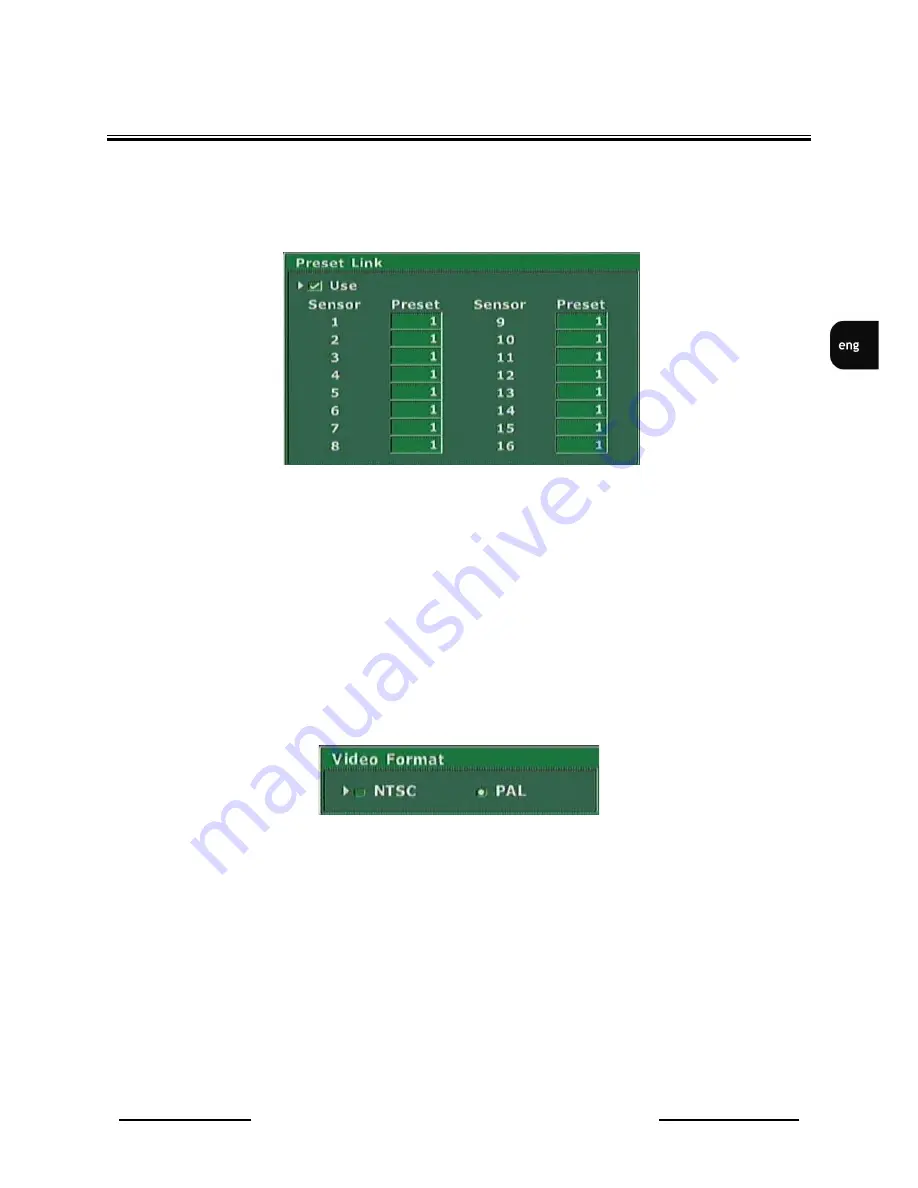
3.1.4 Alarm Presets 


This sub-menu applies only to the PTZ cameras. 


This  sub-menu  is  used  to  select  Speed  Dome  Cameras  preset  which  will  be  activated  for  selected 
camera in case of external sensor activation. 

In example shown above if on external sensor 1 alarm will appear camera connected to input 1 will set 
automatically  in  position  saved  as  a  preset  1  .  Camera  2  after  alarm  on  external  sensor  2  will  set 
automatically in preset number 1 and so on.   

Presets should be defined earlier. PTZ cameras control information can be found in chapter 8. 

To set automatic alarm preset function as active field 

Use 

should be marked

.


3.1.5   Video Format  


When this sub-menu is entered a video system selection window will be displayed on the screen. 

In most European countries PAL system is utilized. For cameras and monitors proper operation , PAL 
option should be marked.  


View for 
NV-DVR900 

Summary of Contents for NV-DVR1600

Page 1: ...NV DVR900 NV DVR900CD NV DVR1600 NV DVR1600CD User s Manual...

Page 2: ...E DONE BY QUALIFIED SERVICE PERSONNEL OF AUTHORIZED NOVUS SERVICE AND CONFORM TO ALL LOCAL CODES WARNING DIGITAL VIDEO RECORDER IS ELECTROSTATIC CHARGES SENSITIVE EQUIPMENT THEREFORE IT SHOULD BE USED...

Page 3: ...e outlet before cleaning This device can be clean only with a clean damp cloth Try to avoid using chemically active liquid cleaners or aerosol In the event of strong dirt it is allowed to use gentle c...

Page 4: ...Settings 22 3 1 4 Alarm Presets 23 3 1 5 Video Format 23 3 2 Recording 24 3 2 1 Recording Schedule 24 3 2 2 Motion detection 25 3 2 3 Manual recording 27 3 3 Sensor Alarm Setup 28 3 3 1 Sensor Name 2...

Page 5: ...Installing the HDD in the swappable bay 67 7 2 USB HDD connecting 67 7 3 IEEE1394 FireWire HDD connecting 68 8 PTZ MODE 69 8 1 Novus and Pelco speed dome cameras controlling 69 8 2 Required menu sett...

Page 6: ...overall CCTV system functionality can be improved 1 1 Main characteristic User friendly interface with functions known from analog Multiplexers Convenient to use Shuttle Jog system for data search The...

Page 7: ...Detection grid 16x16 with adjustable sensitivity settings specific for each camera Event List up to 25 000 events video loss detection power loss disk full motion detection Alarm Inputs 9 TTL inputs...

Page 8: ...otion Detection grid 16x16 with adjustable sensitivity settings specific for each camera Event List up to 25 000 events video loss detection power loss disk full motion detection Alarm Inputs 16 TTL i...

Page 9: ...ly after it has been brought from a place of low temperature If the device has been brought from the area of lower temperature the user should wait until the equipment will slowly warm up and reach th...

Page 10: ...ons described in this manual concerning back panel inputs usage and description Warning Before connecting the device to power supply make sure that the AC SELECT voltage supply switch is set properly...

Page 11: ...de 9 MONITOR main monitor output Composite Video Signal CVS user can select one of various display modes 10 CALL MONITOR call monitor output additional CVS only full display mode 11 FAN device cooling...

Page 12: ...of external devices Monitors cameras and other devices are not included and must be purchased separately Detailed description of devices connection is included in later chapter s of this manual Alarm...

Page 13: ...layed in full mode Pressing these buttons in sequence mode will display in succession different modes of split screen display 3 3 SETUP Multiplexer settings enter buttons OSD On Screen Display menu wi...

Page 14: ...ltiplexer status is indicated by a light diode placed just above the button 7 TRIPLEX In the data playback mode this button turns on simultaneously live display mode of one of the camera channels One...

Page 15: ...fields 12 REV PLAY EXIT In the playback mode this button allows to select playback direction reverse By pressing again the Multiplexer will switch into PAUSE mode In configuration mode this button is...

Page 16: ...Sp z o o 16 16 SIGNAL DIODES Diode marked as a HDD indicates HDD s status LAN diode indicates computer network connection 17 IR RECEIVER The infra red receiver window emitted by IR remote Control Do...

Page 17: ...gn on the monitor screen System Load Procedure takes dozen seconds While its duration none of the front panel buttons or IR Remote Control buttons should be pressed System Load Procedure is finished i...

Page 18: ...r Multiplexer menu settings button SETUP should be pressed In main menu that will be displayed on the screen there are seven sub menus Specific menu functions will be described on next pages of this u...

Page 19: ...vided applying to the camera settings and additionally one video system selection sub menu 3 1 1 Camera Control When this menu is selected and button ENTER is pressed Speed Dome Camera control icons w...

Page 20: ...eillance personnel simply and quickly identify specific monitored areas It can be e g Stairways Door2 HOUSE In general it can be any desired name that will consist of up to 16 characters out of the sy...

Page 21: ...ue of this setting has no influence on system operation In Model field specific menus is used to select one of available telemetry protocols All Speed Dome Cameras connected to the Digital Multiplexer...

Page 22: ...Speed Dome Cameras telemetry protocol The menu Baud Rate is used to select transmission speed The menu Select Terminal is used to select telemetry port to which PTZ commands will be transmitted Port R...

Page 23: ...nnected to input 1 will set automatically in position saved as a preset 1 Camera 2 after alarm on external sensor 2 will set automatically in preset number 1 and so on Presets should be defined earlie...

Page 24: ...g settings 3 2 1 Recording Schedule Digital Multiplexers NV DVR900 and NV DVR1600 provide advanced schedule recording function allowing to set desired recording settings for individual cameras for spe...

Page 25: ...mera selection There is a possibility to define active area and motion detection sensitivity for each camera First select Area then enter Area Define option Grid 16x16 fields will appear on the screen...

Page 26: ...are applied immediately what allows to apply appropriate sensitivity level for given camera Option Common Option is used to set pre and post alarm duration Pre Recording Time option allows to record...

Page 27: ...each of the cameras Letters in first column describe recording mode S sensor M motion detection A continuous no letter camera is not recorded Digits in second column describe data recording resolution...

Page 28: ...ow will include following alarm inputs names It is good to assign names to following alarm inputs as it will help greatly to identify events on Log View list If for example input nr 1 will be named PI...

Page 29: ...e marked then if event occurs on alarm input 1 or 4 or on both simultaneously the defined alarm relay will be activated Activation of remaining inputs will not activate the alarm relay Events option i...

Page 30: ...ted then the alarm will remain active for the period preset in seconds in the window next to it When the preset time passes alarm is deactivated automatically and the Digital Multiplexer returns to th...

Page 31: ...highlighted by blue color For window selection within selected screen these arrow buttons are used selected window will be highlighted by blue color To assign desired camera to selected window one of...

Page 32: ...if image playback is decreased increased slow fast reverse slow fast forward Audio Setup option is used to define following settings Gain this setting allows to adjust recorded signal level depending...

Page 33: ...ed to select one of the listed OSD On Screen Display menu languages Transparency option is used to adjust the appearance of menu windows channels descriptions recording modes etc Depending on this set...

Page 34: ...ns 3 7 1 Log View Log View sub menu provides access to system registry information Registry information proofs valuable tool for diagnostic problems as well as provide important system information eve...

Page 35: ...isplay entire registry Sensor Motion filtering option which if used displays only alarm events and motion detection Disk filtering option which if used displays only HDD events Other filtering option...

Page 36: ...d through FireWire or USB ports are listed Warning POWER OFF Digital Multiplexer before connecting external HDD HDD s information window contains following data For information describing HDD assigned...

Page 37: ...capacity usage which if reached information shown on previous page will appear For example if input value equals 90 then when total system HDD HDD s used space will reach 90 of available HDD HDD s spa...

Page 38: ...d Warning Formatting HDD HDD s will erase all data previously stored on selected HDD s Please use this option with extra caution WARNING Formatting HDD will also cause to format all HDD s with a numbe...

Page 39: ...ll be backup if any recording occurred within the range of pre selected time period on selected channels If option All is not checked then by pressing Select option user can select which specific chan...

Page 40: ...lay on main monitor after pressing Auto button Interval option is used to define split screen dwell time Dwell time can be defined within the range of 300 seconds Channel Selection is used for channel...

Page 41: ...ve channels will be omitted Alarm Sequence option allows to stop sequence display after alarm detection on one of the alarm inputs The device will display image of camera aligned with selected alarm i...

Page 42: ...wing level as well as 2 additional options applying to Multiplexer control Lock Front Button option allows to lock buttons except OPERATE and SETUP on the front panel of the device This can prevent fr...

Page 43: ...43 MULTIPLEXER MENU 3 7 6 1 Network Setup This sub menu is used to configure network connection settings Static IP Subnet Mask Gateway DNS Servers and Web Server Port Number which are used for device...

Page 44: ...and time and the displayed date format y year m month d day On the bottom of the screen current system date and time is displayed 3 7 6 3 Password Administration Sub menu used for adding new user acc...

Page 45: ...le shown on previous page 1 user s is registered User 1 has access to Multiplexer menu Setup PTZ function PTZ start stop recording mode REC playback function PB In order to modify the user authorizati...

Page 46: ...swords only login via computer network is possible During network connection utilizing client program following login window will appear In order to login appropriate user name and password must be in...

Page 47: ...ation on current software version and update please contact device provider 3 7 6 6 Covert Channel Selection Sub menu Covert Channel Selection is used to hide desired video channels If this option is...

Page 48: ...work option allowing sending e mail messages to given mail account utilizing SMTP server inputted in Address option In option Port number mail transmission port number should be set Address list may i...

Page 49: ...his value will define periodicity of e mail notifications It is necessary to check this option in order to receive e mail notifications of no events detection in the system Every Events option defines...

Page 50: ...t any moment Item Selection option is used to select what type of settings we wish to copy Selecting All will backup all settings possible to select Press Backup To USB to start backup to drive curren...

Page 51: ...ine connection settings when remote system keypad is used At the moment of manual preparing remote system keypad is an unavailable option and there is no need any setup in Keypad Setup sun menu 3 7 9...

Page 52: ...schedule for all days will have following look The monitored facility recording settings requirements are as follows Monday Friday continuously recorded will be channels 1 10 in hours 10 18 During th...

Page 53: ...ecording settings edition Select only motion detection recording with maximum speed and resolution settings Leave edition by pressing EXIT Next for each hour quality level 5 and audio recording should...

Page 54: ...ld be used To do this option Copy To should be activated In the Copy Schedule window option Source Channel 1 should be selected and push in channel buttons 2 3 4 5 6 7 8 9 10 to which we intend to cop...

Page 55: ...Thursday and Friday settings by selecting appropriate Days buttons Now appropriate settings needs to be input for Saturday and Sunday To achieve this for example Friday settings should be copied to S...

Page 56: ...t Add In the window that appears mark Enable and set recording time span for these two days Next for each channel except for channel 9 input recording settings All is left is the recording quality set...

Page 57: ...lable the Multiplexer initiates playback of the data with the closest date to the one selected Selecting Play Audio activates audio playback if user initiates video playback The audio playback is avai...

Page 58: ...ctivate recording again one of the button PLAY or R PLAY must be pressed During playback there is a possibility to fast forward playback utilizing SHUTTLE twist handle By twisting clock wise increases...

Page 59: ...DD swappable bay Backup HDD Search should be selected to display HDD contents Individual lines represent backup files On example shown above 3 files can be found If backup HDD is not installed in the...

Page 60: ...idual lines represent backup files On example shown above 3 files can be found on backup CD If a CD writer is not installed in the Multiplexer or there is no backup data available on the CD system wil...

Page 61: ...es can be found Following information is displayed if no alarm recordings occurred Use JOG handle to select appropriate file and press ENTER to initiate playback During recordings playback from CD ide...

Page 62: ...s placed on the front panel of the Multiplexer Switch to full screen display mode Playback desired data and find desired image Again press PLAY button to switch to pause mode In pause mode precisely s...

Page 63: ...possible while backup however the refresh rate is reduced 3 No playback transmission trough the network is possible while backup 4 Backup HDD should be connected directly to the IDE port in PC in ord...

Page 64: ...is reduced 3 No playback transmission trough the network is possible while backup 4 Backup HDD should be connected directly to the IDE port in PC in order to playback Do not use USB or other interface...

Page 65: ...rough the network is possible while backup 4 Backup HDD should be connected directly to the IDE port in PC in order to playback Do not use USB or other interfaces To backup part of the recordings to e...

Page 66: ...al CD RW access the following menu System Setup HDD Backup Start and End option is used to define backup data time span Channel Selection option is used to select the channels from which we intend to...

Page 67: ...removing swappable HDD bay To install HDD in the swappable bay remove the lock using the key purchased with the device next remove the swappable bay from the Multiplexer Open the top cover by pulling...

Page 68: ...operate in none of the RAID modes If both external HDD s and external CD writer are to be connected to the system via one FireWire port CD writer should be connected as the first unit and then additi...

Page 69: ...ion speed must be set for all PTZ cameras in the system review PTZ cameras user s manual for more information The following description applies to connection of Novus and Pelco cameras To connect came...

Page 70: ...US Security Sp z o o 70 PTZ MODE Pelco camera Spectra Video cable Pelco camera Spectra Control cable Multiplexer PELCO cameras connection Novus cameras connection Novus camera CAMA I Video cable Contr...

Page 71: ...sion settings access the menu Camera Setup Pan Tilt Model Set Select Model option to protocol Pelco D Select Baud Rate option identical speed as the one selected in cameras in example shown below 4800...

Page 72: ...Pan i Reverse Tilt option will revert the camera PAN TILT rotation direction activated by SHUTTLE handle twist In specific situations this function can make control more intuitional Image settings Nam...

Page 73: ...nd SHUTTLE handle is twisted the focus function can be adjusted manually Auto Focus if this option is selected and ENTER button is pressed the auto focus option is activated Preset if this option is s...

Page 74: ...e control This procedure description can be found in chapter 10 In order to operate speed dome camera PTZOSD on screen display menu should be activated Press PTZ or access sub menu Camera Setup Camera...

Page 75: ...s 1 8 Similar in the second joint the first pin from the left side is a ground pin G following pins are alarm inputs 9 16 The inputs operate in TTL standard for this reason appropriate current capacit...

Page 76: ...apacity of each relay can not exceed 100mA Directly to relays LED diodes can be connected creating for each relay circuit like shown on the diagram below If system requires connection of external devi...

Page 77: ...l indicator To set indicator to DVR the button STOP on the front panel of the DVR should be pressed and while holding it pressed then press numeric button e g 1 Both buttons should be hold for a perio...

Page 78: ...accordingly to their description Only functions which execution utilizing IR Remote control is different then using front panel buttons are described below PLAY button is used to access playback menu...

Page 79: ...sible Two methods exist of initiating Multiplexer connection with the use of applet downloaded automatically from the Multiplexer described in the user s manual with the use of Multi Viewer software d...

Page 80: ...ring first connection user must accept installation of ActiveX format Previously in the web browser settings in the tab security ActiveX installation should be set to enabled If in the Multiplexer net...

Page 81: ...hort period in the web browser an graphic interface shown below will appear The data playback is possible only in the full window display meaning that only image from one camera can be playback at a t...

Page 82: ...n the recording cameras in any mode limited speeds exist to preset for individual cameras Maximum recording speeds table for NV DVR900 For resolution 360x288 For resolution720x288 View for NV DVR900 Q...

Page 83: ...the recording speed In General depending on the recording cameras in any mode limited speeds exist to preset for individual cameras Maximum recording speeds table for NV DVR1600 For resolution 360x288...

Page 84: ...82 964 1929 3858 5787 7716 9645 11574 15432 30864 2 286 572 1145 2290 4581 6872 9162 11453 13744 18325 36651 1 346 693 1386 2772 5545 8318 11091 13864 16637 22183 44367 Recording time in hours with fo...

Page 85: ...2 3255 4340 8680 17361 3 226 339 678 1356 2034 2712 3390 4069 5425 10850 21701 2 248 372 745 1491 2237 2983 3729 4475 5967 11935 23871 1 271 406 813 1627 2441 3255 4069 4882 6510 13020 26041 Recording...

Page 86: ...NV DVR900 NV DVR1600 ver 2 0 User s Manual All rights reserved NOVUS Security Sp z o o 86 NOTES...

Page 87: ...NV DVR900 NV DVR1600 ver 2 0 User s Manual All rights reserved NOVUS Security Sp z o o 87 NOTES...

Page 88: ...NOVUS Security Sp z o o ul Pu awska 431 02 801 Warszawa tel 22 546 0 700 fax 22 546 0 719 www novuscctv com 2005 05 20...

Reviews: