


Users manual
NR3700-O/G
Revision #:
A
Date:
9-13-16
Page #:
1 of 19
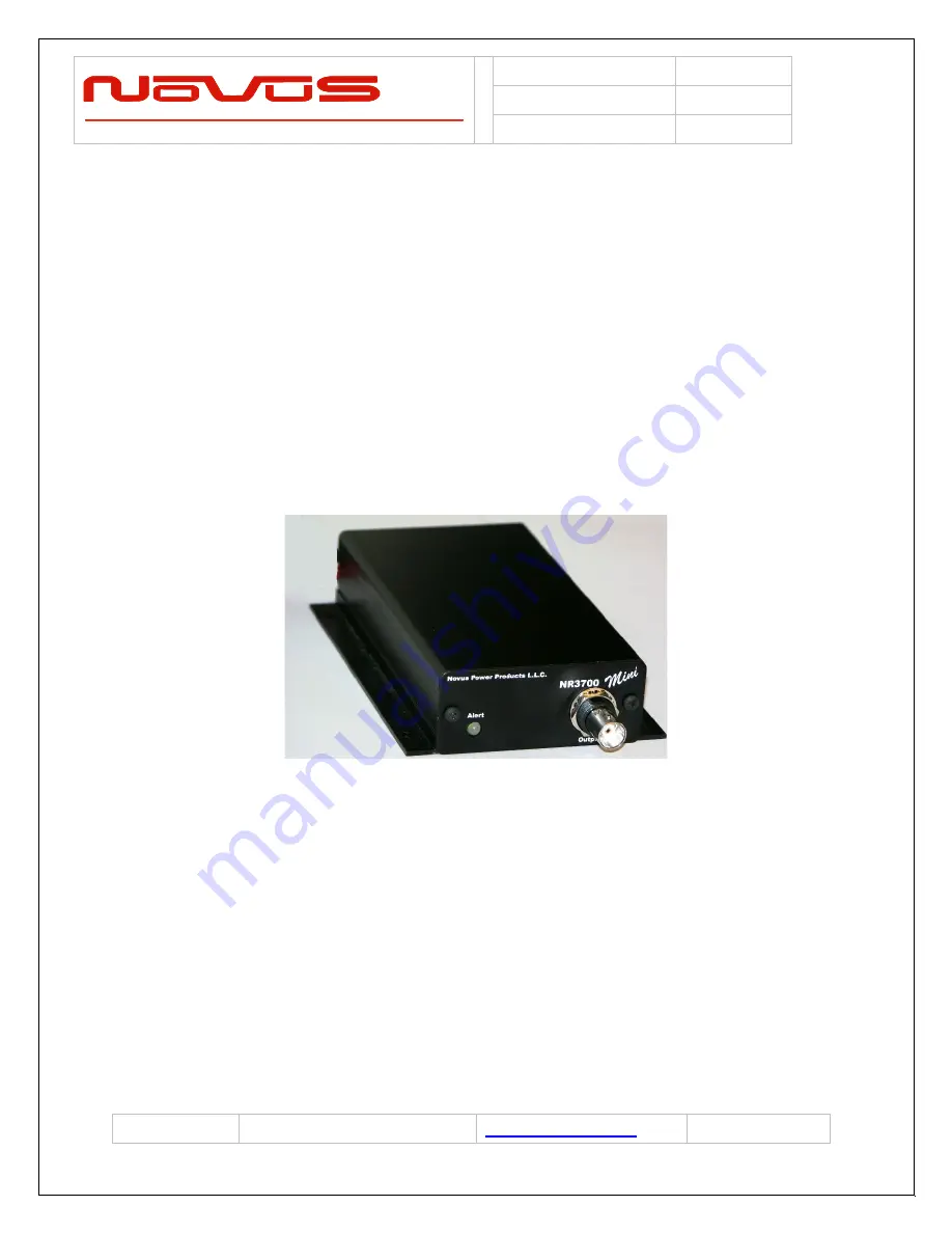
NR3700-O/G
10MHz Frequency Reference, OCXO, GPS/GNSS
Locked Single Channel, Auto-Cal
All information provided herein is the proprietary property of Novus Power Products L.L.C. The
information included may be reproduced without the permission or prior approval of Novus Power
Products L.L.C.for the purpose of operating the Novus equipment.


