background image


USERS MANUAL 

NR2306-O/G 

REVISION 

DATE 

3-8-18 


Page | 14 


There are four settings, and these are the same as the serial command $GPS: 


Setting 

Description 

Serial 

Command 

GPS 1 

GPS 1 is used as output regardless of lock status or error 

$GPS=0 

GPS 2 

GPS 2 is used as output regardless of lock status or error 

$GPS=1 

AUTO (1) 

GPS 1 is default, if locked and no errors, else GPS 2 is used 

$GPS=2 

AUTO (2) 

GPS 2 is default, if locked and no errors, else GPS 1 is used 

$GPS=3 


To cycle through the selections, use the SELECT button.  To save, go to the Save 
Configuration Screen, or use the serial $SAVEFLASH command.  The default setting is 
Auto (1). 


The GPS Select setting also determines the output of the GPS/GNSS specific strings to the 
serial RS232 and the SNMP GPS specific settings.  The strings that follow the specified 
GPS are the RMC, GNS, GSA, GSV, ZDA, and NVS (strings 7 through 11). 


2.9 Save Configuration 


The Save Configuration screen allows the user to save the current settings for Alert 
Threshold, Input Threshold, Attenuation, Input Select, Reference Voltage and any other 
settings that have been modified via the RS232 port. 


To save the current settings, press the SELECT button twice. 
 
The Save Configuration action is equivalent to the $SAVEFL command on the serial port.  
 

2.10 Fault Status 


The Fault Status screen allows a quick overview of any Channel faults from the front panel.  
The total fault count is listed, as well as a visual flashing indication of any channels that are 
beyond the threshold values. 


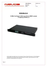
Summary of Contents for NR2306-O-G

Page 1: ...Channel Ultra Low Noise GNSS Locked Frequency Reference All information provided herein is the property of Novus Power Products LLC The information included may be reproduced without the permission o...

Page 2: ...PPS Status 11 2 8 GPS Select Dual Time Base Feature 13 2 9 Save Configuration 14 2 10 Fault Status 14 2 11 UTC Mode 15 2 12 GMT Offset 15 2 13 Power Switch 16 3 0 Rear Panel 16 3 1 Channel Outputs BNC...

Page 3: ...Overview The NR2306 is one of our most versatile and featured references The instrument starts with an ultra low phase noise OCXO The OCXO can be locked to either the GNSS an external PPS external 10...

Page 4: ...h and other effects The internal control loop modulates the OCXO frequency to maintain frequency and minimize the timing difference between the GNSS PPS and the synthesized PPS The PPS output drive ca...

Page 5: ...ote access and control For GNSS locked configurations a dual time base option is offered The second time base effectively controls an embedded frequency counter to confirm that the primary 10 MHz is w...

Page 6: ...ality of the front panel controls and indicators Two buttons above the status LEDs provide navigation through the menus In general the NEXT button advances through the menus to the next screen while t...

Page 7: ...ted on this screen but will not change the NMEA output data 2 2 GNSS Detailed Status The GNSS Status Menu gives the user a quick reference for the quality of the GNSS satellite signal and length of ti...

Page 8: ...isplayed in addition to the actual measured value These values reflect the percentage threshold defined in the Alert Threshold settings If the output value is too low to give a valid reading the displ...

Page 9: ...ble in 5 increments from 10 to 60 Each channel has a Reference Voltage which can be set all at once by latching the channels current value in the Latch Channel Average Screen Each channels reference v...

Page 10: ...is connected to a high impedance input and reports 1 25Vrms at the output The output of Channel 2 is connected to a 50Ohm terminated input and reports 0 90Vrms at the output Alert threshold is set to...

Page 11: ...rt with the FLTTHR command For details on the Alert Threshold see Programmer s Guide 2 6 Latch Channel Values The Latch Channel Values Screen allows the user to save the current channel output values...

Page 12: ...led regardless of Warmup Holdover status PWH 1 Auto Disabled during Warmup disabled after holdover is exceeded Enabled after warmup during valid holdover PWH 2 On PPS is enabled regardless of Warmup H...

Page 13: ...The output configuration required is factory set If a dual GPS GNSS option is installed the currently selected GPS PPS will be noted with an arrow This arrow indicates the actual source of the PPS In...

Page 14: ...g also determines the output of the GPS GNSS specific strings to the serial RS232 and the SNMP GPS specific settings The strings that follow the specified GPS are the RMC GNS GSA GSV ZDA and NVS strin...

Page 15: ...232 serial port The presence of a valid DC input voltage is indicated on this screen as well as a valid AC power input If either of these supplies are not present a FL indication will be shown next to...

Page 16: ...DC input option provides a redundant and automatic back up source in the case of failure of either input 3 0 Rear Panel 3 1 Channel Outputs SMA There are six 10 MHz outputs across the left hand side o...

Page 17: ...V source input this would be the positive output from the DC source Pin C goes to the Earth ground of the DC source 3 4 AC Input The AC input accepts 90 250Vac 50 60Hz IEC 320 C14 compliant 4 0 GNSS R...

Page 18: ...rrors especially when a change in height does occur A 2 D position fix is not considered a good or accurate fix it is simply better than nothing The receiver s antenna must have a clear view of the sk...

Page 19: ...nto space This assumes the satellite and receiver timing to be identical In reality when the receiver compares the incoming signal with its own internal copy of the code and clock the two will no long...

Page 20: ...lash to reflect all current settings Table 1 shows a complete list of input commands and descriptions that are handled by the internal processor In general a command may be input without or an additio...

Page 21: ...d flash settings The NMEA output is a combined structure of the GNSS receiver output and the onboard processors status output The commands from the Programmers Guide are implemented on the RS232 port...

Page 22: ...e 85 1 Hz 140 10 Hz 150 100 Hz 160 1000 Hz PPS 15ns 1 sigma 3 3 volt logic or 5Vdc PPS Jitter Stabilized 1 ns pp GNSS Receiver 26 Channel GNSS Power requirements 10 watts 90 to 250Vac 50 60 Hz Connect...

Page 23: ...airing or issuing a credit at its option for any such item returned by Buyer under the terms of this warranty EXCLUSIONS The above warranty shall not apply to defects resulting from improper or inadeq...

Reviews: