Novus NMS NVR M5 User Manual Download Page 20

NMS NVR M5, NMS NVR M7 

User’s manual ver.1.0 

NVR MENU 

All rights reserved © AAT HOLDING S.A. 


20 


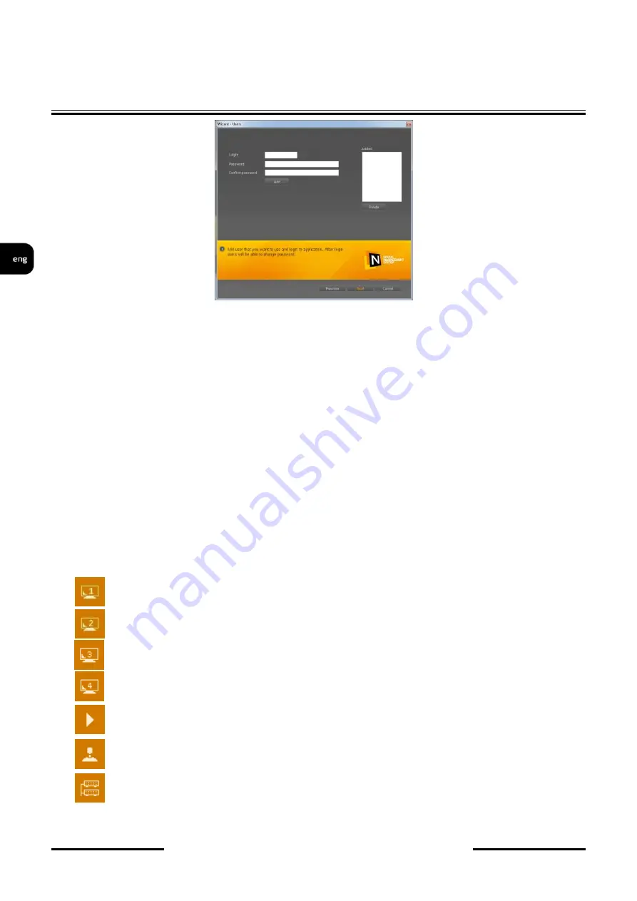
Entering  required  data  (login  and  password)  and  pressing  the  “Add”  button  moves  an  edited 

account  to  the  “Added”  box.  When  an  incorrect  user  entry  has  been  performed,  an  account  may  be 
deleted by pressing the “Delete” button.  
 

After  adding  required  user  accounts  and  pressing  the  “Next”  button  a  final  window  is  then 

opened, allowing to apply selected changes and save them in software configuration. In order to apply 
settings, user is automatically logged out and then prompted to log in again. 
 

9.1.3. Graphic interface: information 


NMS interface consists of movable panels whose functions are described below. Details will be 

presented in the following chapters of the user’s manual. You can adjust panel layout: move, enable or 
disable,  link  and  change  the  panels’  size  what  gives  you  practically  unlimited  possibilities  of 
modifying  the  layout  according  to  your  needs  or  preferences.  The  interface  layout  is  saved  and  is 
restored by default when NMS is run again.  A movable window, which  you can modify (change its 
size, or functions in NMS modules) is called a panel. 


NMS includes the following modules: 

1. 

Video panel 1 

real time video or playback display 

2. 

Video panel 2 

real time video or playback display 

3. 

Video panel 3 

real time video or playback display 

4. 

Video panel 4 

real time video or playback display 

5. 

Playback

 - selecting the recording to be played 

6.

 PTZ panel 

- PTZ camera control panel 

7. 

Devices

 - selecting and displaying status of IP devices 

Summary of Contents for NMS NVR M5

Page 1: ...user s manual NMS NVR M5 NMS NVR M7...

Page 2: ...rical and electronic equipment for recycling purpose For more information about recycling of this product please contact your local authorities your household waste disposal service or the shop where...

Page 3: ...to heat build up and damaging the device itself as a consequence 9 Mounting the device on unstable surface or using not recommended mounts is forbidden Improperly mounted device may cause a fatal acci...

Page 4: ...r Screws User s manual 2 MAIN CHARACTERISTICS 4 x Ethernet PoE IEEE802 3af 15 4W RJ 45 interface 10 100 Mbit s Video and audio channels 16 Recording speed up to 480 fps at 1280 x 720 Recorded stream s...

Page 5: ...4 x 12 fps for 2592 x 1944 270 fps 9 x 30 fps for 1280 x 720 90 fps 3 x 30 fps for 1920 x 1080 45 fps 3 x 15 fps for 2048 x 1536 36 fps 3 x 12 fps for 2592 x 1944 Recorded Data Search by date time eve...

Page 6: ...NMS NVR M5 NMS NVR M7 User s manual ver 1 0 All rights reserved AAT HOLDING S A 6 FOREWORD INFORMATION 3 1 Dimensions All dimensions are in mm...

Page 7: ...tors USB Ports POE Switch Anti vibration bracket Audio input Audio output Ethernet Ports Power ignition module connectors PS2 port DC IN port VGA DVI monitor output COM port 1 4 Digital I O USB Ports...

Page 8: ...g the antivibration kit to ground NVR should be placed on the flat surface Due to requirements device can be mounted by Screwing rivet screw 1 from the ground Screwing to the ground using universal ho...

Page 9: ...PUT DC S3 Connection sheme is shown below Connect the power source battery and ignition ACC IN signal to DC Input The minimal recommended cable diameter not including insulation is 2 59 mm 10 AWG The...

Page 10: ...onally plug the appropriate cable to the S3 connector in the ignition module and the NVR unit as shown on the pictures below The cable is included DC IN 9V 30V 1 V 2 V 3 Ground 4 Ground 5 Ground S3 1...

Page 11: ...ion of the power supply voltage SW1 DIP Switch 3 Dip Switch 4 SW1 DIP Switch 1 DIP Switch 2 Turn On Turn Off Remark 00 0 off 0 off 11 5V 10 5V Default 01 0 off 1 on 12V 11V 10 1 on 0 off 12 5V 11V 11...

Page 12: ...1 0 off 1 on 24V 10 1 on 0 off 19V 11 1 on 1 on 12V SW2 DIP Switch 1 Function Remarks 0 0 off Default 3 seconds delay Default 1 1 on Configuration on the DIP Switches 3 4 5 DIP Switch 3 4 5 Turn on de...

Page 13: ...ignition module 7 FIRST LAUNCH CAUTION English is default language For changing the language follow the steps described further in this chapter First launch requires additional action User will be ask...

Page 14: ...tton to run NMS full description in chapter 9 1 press the Turn off button to close NMS and show the main screen description in chapter 9 press the X button in right upper corner to close this window w...

Page 15: ...tion requires an additional login Access to these options is assigned only to an administrator account root Access from other accounts with administrator privileges is restricted The default login is...

Page 16: ...on which is is a professional solution for video monitoring based on TCP IP CLIENT SERVER networks A wide range of NMS server settings for video streams sharing enables creation of complex monitoring...

Page 17: ...of the main screen there is a field indicating the status of NMS Possible statuses are Starting Running Closing Stopped NMS login window is shown below Default user is root Turn off button closes the...

Page 18: ...features Server processing power is mainly used to record streams from the cameras video streaming to NMS Client video display is limited Server Client processing power is is used to record and displ...

Page 19: ...etwork or not function available only in server and server client modes This function has its significance when installing the NMS in server mode Option is skipped in client mode Pressing the Next ope...

Page 20: ...tions are described below Details will be presented in the following chapters of the user s manual You can adjust panel layout move enable or disable link and change the panels size what gives you pra...

Page 21: ...isplay up to 4 streams per window The second video window is also used by LOGS MAPS and EVENTS panels Logs panel PTZ panel Devices and cameras panel Live video and playback panel Application menu Appl...

Page 22: ...ity for video window display purposes in order to save computing power of a NVR Split screen stream option is configurable in CONFIGURATION DEVICES General tab Split screen streams are shown as greyed...

Page 23: ...es of all video streams associated with IP device State The IP device status connected disconnected and associated video streams status recording on off recording mode snapshoot playback active PTZ co...

Page 24: ...d Icon displayed on NMS Client application shows recording available on NMS Server Schedule mode enabled grey icon means that recording is disabled Live view enabled Playback on PTZ camera control on...

Page 25: ...device or NMS server Date and Time Current NMS server time Initialization attempting to open a video stream Incompatible device Connection error device incompatible with the NMS software Connection li...

Page 26: ...evice panel allows user to display selected video stream in desired window by clicking RMB and choosing Show position in menu Position 1 means that first screen in division isn t displaying any video...

Page 27: ...ws in division cause that some streams will not be displayed 9 1 7 NMS user manual Chapter 9 1 and subchapters contain basic information about using the NMS Detailed information can be found in the fu...

Page 28: ...splays a Nwatch window It is a diagnostic application monitoring the performance of the NMS It contains information about CPU usage number of threads used memory application state and log list 9 3 Men...

Page 29: ...or via the Internet IPTool utility to find cameras and change their network parameters Remote support runs Team Viewer application In order to get the remote support contact the Novus technical suppor...

Page 30: ...ns processes CPU usage commit charge and memory information network activity and statistics logged in users and system services Change password allows to change the access password for default user ro...

Page 31: ...n changing In order to change the screen resolution select the Control panel from the System configuration submenu In Display 1 panel press the Adjust resolution 2 In window Screen Resolution choose d...

Page 32: ...ked no 3 on the photo in chapter 3 2 of this manual After pressing wait until operating system shutdown User can be prompted to log out of the NMS The device could be also shutdown from the main scree...

Page 33: ...NMS NVR M5 NMS NVR M7 User s manual ver 1 0 NOTES All rights reserved AAT HOLDING S A 33...

Page 34: ...2015 12 11 JM MK AAT Holding sp z o o 431 Pulawska St 02 801 Warsaw Poland tel 4822 546 07 00 fax 4822 546 07 59 www novuscctv com...

Reviews: