


N1540
NOVUS AUTOMATION
2
difk
Alarm of the maximum differential value. It triggers when
the PV value is
above
the point defined by:
ALrF+SPA1
(using alarm 1 as an example).
ALrF
PV
ALrF + SPA1
ALrF
PV
ALrF + SPA1
SPA1 positive
SPA1 negative
ierr
Sensor breaks alarm. It is activated when the Input
presents problems such as interrupted sensor, bad
connection, etc.
Table 2 –
Alarm functions
Note
: The figures are also valid for Alarm 2 (SPA2).
Important note:
Alarms configured with the
ki
,
dif
and
dif.k
functions also trigger their associated output when a sensor fault is
identified and signaled by the digital panel meter. A relay output, for
example, configured to act as a High Alarm (
ki
), will operate when
the SPAL value is exceeded and when the sensor connected to the
input is broken.
ALARM BLOCKING INITIAL
The
Initial
Blocking
option inhibits the alarm from being recognized
if an alarm condition is present in the process when the digital panel
meter is first energized. The alarm will be enabled only after the
occurrence of no alarm condition.
The initial blocking is useful, for example, when one of the alarms is
set up as a minimum value alarm, which may cause the activation of
the alarm soon upon the process start-up; an occurrence that may be
undesirable in many cases.
The initial blocking is not valid for the
ierr
(Sensor Break) function.
OFFSET
Allows fine adjustments to the PV indication, correcting measurement
errors that appear, for example, after the replacement of the
temperature sensor.
MAXIMUM AND MINIMUM
The digital panel meter memorizes the measured maximum and
minimum values (peak and valley). The operator can observe these
extreme values at any time. These two values are shown when
pressing the
F1
(maximum) and
F2
(minimum) keys. Pressing both
keys simultaneously will clear the memory for a new peak and valley
detection.
To clear the stored values and begin a new cycle of monitoring
endpoints, just press the
F1
and
F2
keys
simultaneously
. When
turn off, the digital panel meter this information is not saved.
CUSTOM LINEARIZATION
This feature allows accurate measurement of the input signals with
non-linear features.
Linearization consists in dividing the calibration curve of the input
signal into segments of variable gain. Each segment consists of a
start and an end. For each input value (
Inp
.xx), a respective output
indication (
ovP
.xx) is defined.
The input signal must present an always-crescent.
Applied to 0-20 mA, 4-20 mA, 0-50 mV, 0-5 V and 0-10 V input types.
24 VDC AUXILIARY VOLTAGE SOURCE
The standard version of the
N1540
provides an auxiliary power
supply for exciting field transmitters (terminals 11 and 13 on the rear
panel).
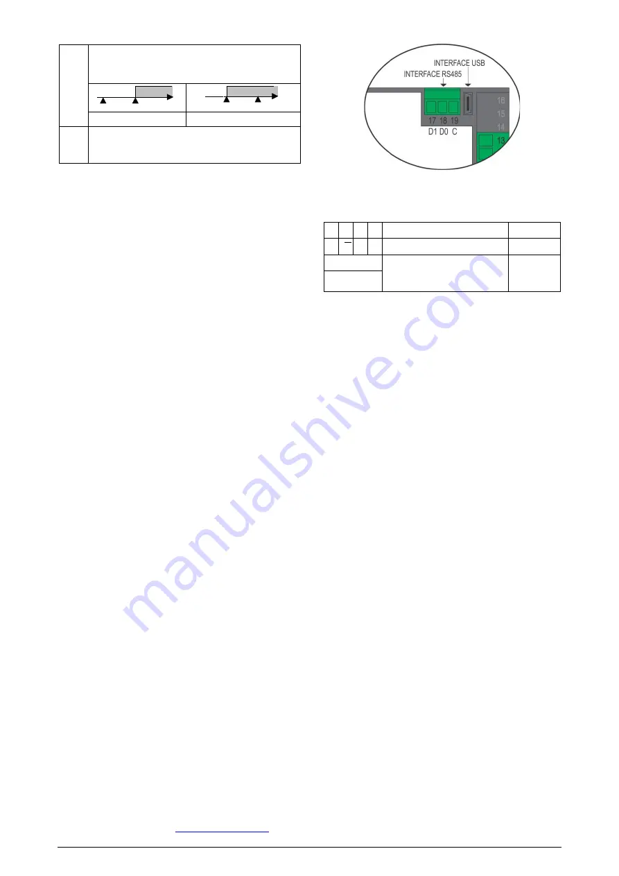
SERIAL COMMUNICATION
Follows a description of the usual communication registers. For full
documentation, download the
Registers Table N1540 for Serial
Communication
Figure 1 –
Serial communication
RS485 INTERFACE: ELECTRICAL CONNECTION
The RS485 signals are:
D1 D D + B
Bidirectional data line.
Terminal 17
D0
𝑫𝑫
D - A
Inverted bidirectional data line.
Terminal 18
C
Optional connection that
improves the communication
performance.
Terminal 19
GND
Table 3 –
RS485
USB INTERFACE
The USB interface is used to CONFIGURE, MONITOR or UPDATE
the controller FIRMWARE. The user should use
QuickTune
software, which offers features to create, view, save, and open
settings from the device or files on the computer. The tool for saving
and opening configurations in files allows the user to transfer settings
between devices and perform backup copies.
For specific models,
QuickTune
allows to update the firmware
(internal software) of the controller via the USB interface.
For MONITORING purposes, the user can use any supervisory
software (SCADA) or laboratory software that supports the Modbus
RTU communication over a serial communication port. When
connected to a computer USB, the controller is recognized as a
conventional serial port (COM x).
The user must use
QuickTune
software or consult the DEVICE
MANAGER on the Windows Control Panel to identify the COM port
assigned to the controller.
The user should consult the mapping of the Modbus memory in the
controller communication manual and the documentation of the
supervision software to start the MONITORING process.
Follow the procedure below to use the USB communication of the
device:
1.
Download
QuickTune
software from our website and install it on
the computer. The USB drivers necessary for operating the com-
munication will be installed with the software.
2.
Connect the USB cable between the device and the computer.
The controller does not have to be connected to a power supply.
The USB will provide enough power to operate the communica-
tion (other device functions may not operate).
3.
Run the
QuickTune
software, configure the communication and
start the device recognition.


