


NOVUS AUTOMATION
1/7
N1030T Controller
TEMPERATURE CONTROLLER AND TIME – INSTRUCTIONS MANUAL – V1.0x A
SAFETY ALERTS
The symbols below are used on the equipment and throughout this
document to draw the user’s attention to important operational and
safety information.
CAUTION:
Read the manual thoroughly
before installing and operating
the equipment.
CAUTION OR DANGER:
Electrical shock hazard
All safety related instructions that appear in the manual must be
observed to ensure personal safety and to prevent damage to either
the instrument or the system. If the instrument is used in a manner not
specified by the manufacturer, the protection provided by the
equipment may be impaired.
INSTALLATION / CONECTIONS
The controller must be fastened on a panel, following the sequence
of steps described below:
•
Prepare a panel cut-out of 46 x 46 mm;
•
Remove the mounting clamps from the controller;
•
Insert the controller into the panel cut-out;
•
Slide the mounting clamp from the rear to a firm grip at the panel.
RECOMMENDATIONS FOR THE INSTALLATION
•
All electrical connections are made to the screw terminals at the
rear of the controller.
•
To minimize the pick-up of electrical noise, the low voltage DC
connections and the sensor input wiring should be routed away
from high-current power conductors. If this is impractical, use
shielded cables. In general, keep cable lengths to a minimum.
•
All electronic instruments must be powered by a clean mains
supply, proper for instrumentation.
•
It is strongly recommended to apply RC'S FILTERS (noise
suppressor) to contactor coils, solenoids, etc. In any application it
is essential to consider what can happen when any part of the
system fails. The controller features by themselves can not
assure total protection.
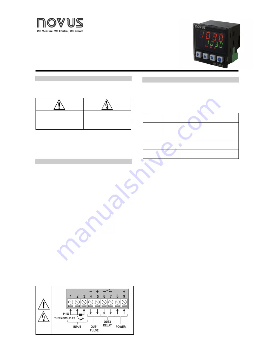
ELECTRICAL CONNECTIONS
Fig. 01
below shows the electrical terminals of the controller:
Fig. 01
- Connections of the back panel
FEATURES
INPUT SINGNAL (INPUT)
The type of input to be used by the controller is defined in the
equipment configuration.
Table 01
displays the input options
available to the user, one of which must be selected during the
controller configuration
.
TYPE
CODE
RANGE OF MEASUREMENT
Termocouple
J
Tc j
Tc j
Tc j
Tc j
Range: -110.0 a 950.0 °C (-166.0 a 1742 °F)
Termocouple
K
Tc k
Tc k
Tc k
Tc k
Range: -150.0 a 1370 °C (-238.0 a 2498 °F)
Termocouple
T
Tc t
Tc t
Tc t
Tc t
Range: -160.0 a 400.0 °C (-256.0 a 752.0 °F)
Pt100
Pt
Pt
Pt
Pt
Range: -200.0 a 850.0 °C (-328.0 a 1562 °F)
Table 01
– Input types
The temperature sensor used should be the first information passed
onto the controller. A change in this parameter may imply automatic
changes to many other parameters. The user must check the general
condition of the configuration whenever an exchange of the sensor
type is held.
OUTPUTS
The controller offers two output channels: OUT1 and OUT2. Their
electrical characteristics are:
OUTPUT
OUT1
- Logical pulse, 5 Vdc / 25 mA
OUTPUT
OUT2
- Output Relay SPST-NA / 1,5 A / 240 Vac
The output channels are user configurable as
Control Output
,
Alarm Output
or as
Output Timers T1
or
T2
.
CONTROL OUTPUT (
(TRL
(TRL
(TRL
(TRL
)
The process control output can operate in
ON/OFF
mode or in
PID
mode.
To operate in
ON/OFF
mode, the value defined in the parameter
PB
PB
PB
PB
should be
0.0
.
With values other than zero in the
PB
PB
PB
PB
parameter, the controller
operates in the
PID
mode. The PID parameters can be automatically
determined enabling the auto-tuning function (
ATvN
ATvN
ATvN
ATvN
).


