

•
3
•
Text in CAPITALS refer to a front panel control or legend (even though the
name of the control may actually be in lower case on the front panel). It
could be a knob or button. For example, FREQUENCY refers to the Filter
frequency control knob. MENUS refers to the Menu Mode button.
The fastest way to become familiar with the product is to follow this quick
start guide. It covers connecting up to audio equipment, listening to the
factory preset sounds, selecting sounds, editing a sound and saving a
sound into a memory location.
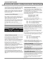
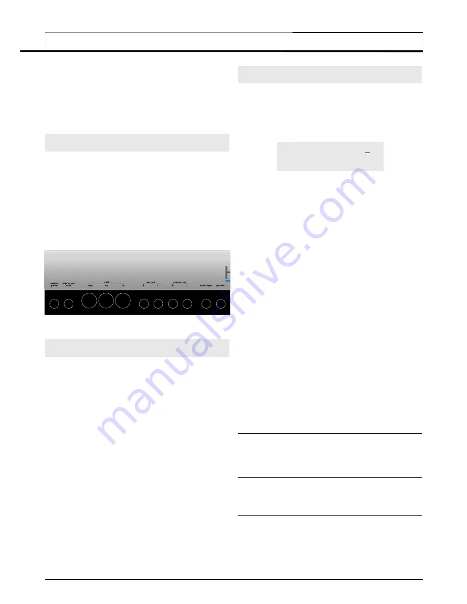
Connecting to Audio and MIDI equipment
Before connecting to other units in the system, ensure the power to all
units is off. Connect an audio cable from the Left and Right master output
sockets to a suitable amplifier or mixing desk stereo inputs.
I
f MONO
operation is required, either output may be used.
Connect the power cable to the socket ‘Power In’ and connect the cable
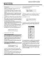
to the AC mains. Switch on the power. The display will show the name of
the last selected Program, Drum Map or Performance and its number.
Select
Program Mode
by pressing the PROG button.
Finally, switch on the other units in the Audio system (amplifier, mixer
etc.).
Listening to the factory preset sounds
Set the VOLUME control to a reasonably high output level. This will main-
tain a good signal to noise ratio. Make sure that the input volume setting
on the system amplifier or mixer is initially set to zero.
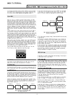
On leaving the factory, the KS Rack is set to receive MIDI information on
Channel 1, so, if using an external master keyboard or sequencer to trig-
ger the sounds, ensure that it is set to transmit on this MIDI channel.
Playing a connected master keyboard or sequencer will result in the cur-
rently selected factory preset sound being heard.
A full listing of the factory preset Programs, Drum Maps and
Performances can be found on page 59. The first few locations of the
user Programs in bank 3 (Program Number 300 onwards) contain initiali-
sation examples. These are also described in the list.
On leaving the factory, the KS Rack has been configured to automatically
select Performance 100 once it is turned on (It is possible to override this
so that the KS Rack automatically selects the Program, Drum Map or
Performance of your choice - see page 50).
The first 50 Performances have been configured at the factory to show-
case some of the impressive features available on the KS Rack. To
inspect the factory set Performances, refer to the Selecting Performances
section of this manual on page 4. These Performances are listed in detail
on page 60.
Selecting Programs and Drum Maps
There are two main modes of operation -
Program Mode
where the
machine is mono-timbral (only one type of sound is available for playing)
and
Performance Mode
where the machine is four Part multi-timbral (up
to four different sounds can be played simultaneously).
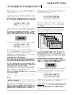
Program Mode is selected by pressing the PROG button. The LED above
the button lights to confirm that Program Mode is selected. The standard
Program Mode display will be shown.
Program’s name 101
Category Name
Program Mode is convenient for auditioning individual sounds.
Standard Programs are organised into four banks, each bank containing
100 sounds. These are referred to as banks 1, 2, 3 and 4.
Bank 1
100 - 199 - First bank of factory preset sounds
Bank 2
200 - 299 - Second bank of factory preset sounds
Bank 3
300 - 399 - First bank of user sounds
Bank 4
400 - 499 - Second bank of user sounds
The next four banks contain four Drum Maps. Drum Maps are whole kits
of percussion sounds, each sound corresponding to an individual note on
the keyboard. A Drum Map is a ‘batch’ of 49 Programs. Each of these
sounds has been programmed to closely immitate the sound of a real or
electronic type of percussion sound, be it a Bass Drum, Snare Drum etc.
Following the 49th Drum Map Program is an extra Program containing the
Effects settings used by the Drum Map as a whole.
A Drum Map may be selected at any time by pressing the DRUM EDIT
button. The last selected drum bank will then be available on the key-
board to audition.
When any Program in a Drum Map is selected, all other Programs located
in the same Drum Map are also available for playing on the keyboard.
To return to a normal Program, select a program between 100 and 499
The Drum Maps available are :
Bank 5
500 - 549 - First factory preset Drum Map
Bank 6
600 - 649 - Second factory preset Drum Map
Bank 7
700 - 749 - First user Drum Map
Bank 8
800 - 849 - Second user Drum Map
There are four methods of selecting Programs, Drum Maps or
Performances. Before using any of the methods, Ensure that a Menu is
not active (the LED above the MENUS button must not be lit). If a Menu
is selected, press the PROG button to select
Program Mode.
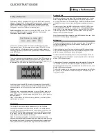
1 - Using the 0 - 9 Keypad buttons
There must always be a three digit entry on the numeric keypad, for
example : To select Bank 1 sound 8, press the
1, 0
and
8
buttons. The
display will now show the name of the newly selected sound and indicate
that sound
108
has been selected.
2 - Using the PAGE buttons
The PAGE buttons may be used to move up or down to the next Program.
Pressing and holding either button for a short period will cause the
Program / Performance number to advance / decrease by a further 9.
3 - Using the PERF / PROG / DATA knob
The DATA knob may be used to move up or down to the next Program.
Turning the knob slowly will advance the selection by one by one. Turning
the knob more quickly will increase the rate of selection.
If the the end of a Program bank has been reached, the first Program of
the next bank will be selected, for example Program 199 moves to
Program 200.
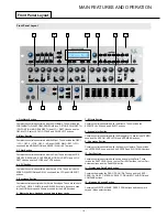
QUICK START GUIDE
Connecting audio equipment - Listening to preset sounds - Selecting Programs