20
WAAS GUS Signal Generator User Guide Rev 1
Chapter 3
Setup Considerations
3.1.5
Initiated Built in Test (IBIT)
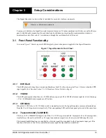
IBIT is performed at power-up or upon a hardware reset. IBIT includes ROM and RAM testing. The front panel
specifies whether the L1 or L5 IBIT passed or failed. A green LED signifies an IBIT pass and an unlit LED
signifies an IBIT failure.
3.1.6
1PPS
The 1PPS LEDs are green and will cycle on and off at a 1 Hz rate to indicate the presence of a 1PPS output signal.
3.2
Rear Panel Functionality
The connections on the rear panel and their connector types are shown in
.
Figure 8: Close-up of Connectors on Rear Panel
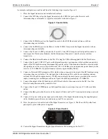
Each connector is keyed to ensure that the cable can be inserted in only one way, to prevent damage to both the
Signal Generator and the cables. Furthermore, the connectors that are used to mate the cables to the Signal
Generator require careful insertion and removal. Observe the following when handling the cables.
• To insert a cable, make certain you are using the appropriate cable for the port - the serial cable has a
different connector (DB9) than the PPS cable (TNC), or the RF cable (N-Type) connectors.
3.2.1
Power
After initial connection of the power supply to the Signal Generator and pressing the power switch on the back of
the unit (see Figure 8 above), the Power LED on the front of the unit (see Figure 7 on Page 19) glows green.
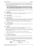
The Signal Generator requires an input supply voltage that comes from a normal power source of 120 volts AC at
60 Hz or 230 volts AC at 50 Hz through its 3-pin (hot, neutral and ground) power connector.
Note:
Where marked L1/L5, the top row of connectors is for the L1
signal and bottom row of connectors is for the L5 signal. Likewise
for the 10 MHz In/Out, the top connector is the Input and the bottom
is the Output.
DO NOT PULL DIRECTLY ON THE CABLES.
For safety reasons, ensure the 3-pin AC power plug is connected to a properly grounded AC
mains supply.


