Nova Florida DELFIS Monothermal Installation, Use And Maintenance Manual Download Page 24

24

Instructions for the installer


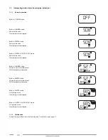
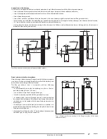
3.3  Positioning the boiler

Each boiler is supplied with a paper template, found inside the packaging (see Fig. 5 Paper template).
The template allows you to ensure that the pipes connected to the CH system, the DHW system and the gas mains, and the air intake/flue gas 

venting ducts are all laid out correctly during the realisation of the water system and before installation of the boiler.
This template is made of heavy-duty paper and must be fixed, with the help of a level, onto the wall where the boiler is to be mounted.
The template provides all the indications required to drill the boiler mounting holes to the wall, procedure which is done using two screws 

and wall blocks.
The lower area of the template shows where to mark the exact point at which the couplings are to be positioned for boiler connection to the 

gas supply pipe, cold water mains supply pipe, hot water outlet, CH flow and return pipes.
The upper area of the template shows where flue gas ducts are to be positioned.

 DANGER

In the case of proximity with flammable walls and passages through walls, apply insulating material between the wall and the flue 

gas venting duct.

IT

ES FR PL PT RU NL DE GB GR RO CZ HU TR

1

Tiraggio

naturale

Tiro

natural

Tirage

naturel

iąg

naturalny

Tiragem 

natural

Natuurlijke

trek

Schornstein-

zug

Natural

draught

Φυσικός 

ελκυσμός

Tiraj

natural

Přirozený tah

Kémény

Bacalı

2

Tiraggio

forzato

Tiro

forzado

Tirage

forcé

iąg

wymuszony

Tiragem 

forçada


Geforceerde

trek

Raumluftu-

nabhängig

Forced

draught

Αναγκαστικός 

ελκυσμός

Tiraj forat

Nucený tah

Ventilátor

Hermetik fanlı

C

Uscita acqua

calda sanitaria

Salida agua

caliente sani-

taria

Sortie eau

chaude sani-

taire

Wyjście ciepłej

wody 

użytkowej

Saída de 

água quente 

sanitária

   Uitgang warm 

tapwater

WW

(Auslauf War-

mwasser)

DHW

Έξοδος 

θερμού νερού 

οικιακής

Ieire apă cal-

dă menajeră

Výstup TPV

HMV 

csatlakozás

Sıcak su

çıkı

F

Ingresso 

acqua fredda 

sanitaria

Entrada agua 

fría

Eau froide

sanitaire

Wejście

wody zimnej

Entrada de 

água

fria


Ingang koud

tapwater

KW

(Einlauf Kal-

twasser)

Domestic 

cold water

Είσοδος 

ψυχρού νερού

Intrare apă 

rece

Přívod 

studené vody

Hidegvíz 

csatlakozás

Soğuk

su giri

R

Ritorno 

impianto 

riscaldamento

Retorno 

instalación 

calefacción

Retour instal-

lation

Powrót 

systemu 

ogrzewania

Retorno do 

sistema de 

aquecimento


Terugvoer 

verwarming-

sinstallatie

RL

(Rücklauf 

Heizanlage)

CH return

Επιστροφή 

εγκατάστασης 

θέρμανσης

Retur 

instalaie 

încălzire

Vratné 

potrubí ÚT

Fűtési 

rendszer 

visszatérő 

csatlakozás

Kalorifer 

dönü

M

Mandata 

impianto 

riscaldamento

Ida 

instalación

calefacción

Départ 

installation 

Zasilanie 

systemu 

grzewczego

Ida do sistema 

de 

aquecimento


Toevoer 

verwarming-

sinstallatie

VL

(Vorlauf Hei-

zanlage)

Προσαγωγή 

εγκατάστασης 

θέρμανσης

Tur instalaie 

încălzire

Průtok vody

Fűtési 

rendszer 

előremenő 

csatlakozás

Kalorifer

gidi

G

Ingresso 

gas

Entrada gas

Entrée gaz

Wejście gazu Entrada de gás


Gasingang

Gas

(Gaseinlass)

Gas inlet

Είσοδος 

αερίου

Racord gaz

Přívod plynu

Gázcsat-

alkozás

Gaz

0DIMACAR24

Fig. 5 Paper template

Summary of Contents for DELFIS Monothermal

Page 1: ...DELFIS Monothermal INSTALLATION USE AND MAINTENANCE EN Translation of the original instructions in Italian IST 04 C 404 01...

Page 2: ...ler is installed Boiler takes the air necessary to combustion directly from the installation premises and features a wind proof flue Due to a lower efficiency any other use of this boiler must be avoi...

Page 3: ...pecific waste management sites After removing the packaging make sure that its elements clips plastic bags foam polystyrene etc are note left within the reach of children as they are potential hazard...

Page 4: ...d windows Contact a Service Centre a qualified installer or the gas supply company Never use a flame to locate a gas leak The boiler is designed for installation in the countries indicated on the tech...

Page 5: ...ir intake and flue gas venting system 25 3 6 Checking combustion efficiency 28 3 7 Connection to gas mains 28 3 8 Hydraulic connections 29 3 9 Connection to electrical mains 29 3 10 Connection to ambi...

Page 6: ...g 5 Paper template 24 Fig 6 Connections to the chimney of open chamber models 27 Fig 7 Dimensions for connection to the flue gas system of the open chamber models 27 Fig 8 Connection to gas mains 28 F...

Page 7: ...4 ERP and Labelling data 22 Tab 5 Limits to be set for TSP parameters and default values in relation to boiler type TSP0 I 31 Tab 6 Limits to be set for TSP parameters and default values in relation...

Page 8: ...G 9 3 4 E Fig 1 Control panel A DHW setting DHW B Parameter confirmation and information request C Operating status selection D Alarm reset and back to the starting page during parameter selection E...

Page 9: ...e is confirmed 4 Alphanumeric indicator Temperature parameter values and fault indication Not used 5 Central heating indicator Boiler is in heating mode Displaying of the heating temperature set point...

Page 10: ...in CENTRAL HEATING ONLY mode No active function Flow temperature displayed Boiler in SUMMER mode Domestic hot water withdrawal DHW temperature displayed Boiler in WINTER mode Domestic hot water withdr...

Page 11: ...ode To select the boiler operation mode press C Operating mode selection Whenever button is pressed the following modes are enabled in sequence SUMMER WINTER CH ONLY OFF SUMMER operating status When t...

Page 12: ...otection function When the heating water temperature sensor detects a water temperature of 5 C the boiler switches on and stays on at its minimum heat output until the temperature reaches 30 C or 15 m...

Page 13: ...ely the desired theoretical temperature During temperature setting the fictitious ambient temperature symbol flashes on the display and the value being set is shown For optimal curve adjustment a posi...

Page 14: ...entre or qualified personnel for maintenance WARNING If the burner shuts down frequently there is a recurring malfunction so contact a service centre or a qualified service engineer 1 4 2 Shut down du...

Page 15: ...frequently occur it means there is boiler malfunction in progress Contact qualified personnel or an authorised service centre for maintenance DANGER Make sure you close filler cock A carefully after f...

Page 16: ...iler from to power mains 1 5 Maintenance WARNING The boiler must be serviced periodically as indicated in the relevant section of this manual Appropriateboilermaintenanceensuresefficientoperation envi...

Page 17: ...ally protected control panel Integrated modulating electronic safety board Electronic ignition and ionisation flame detection device Stainless steel atmospheric burner that can run on several gases Mo...

Page 18: ...flame propagation function CH thermostat timer 240 seconds adjustable Heating pump post circulation function in CH freeze protection and flue cleaning modes 30 seconds adjustable DHW post circulation...

Page 19: ...s and dimensions 2 2 Dimensions 400 700 232 118 250 66 60 62 67 82 63 114 31 91 81 M C G F R Fig 3 Model CTN dimensions M CH system flow 3 4 C DHW outlet 1 2 G Gas inlet 1 2 F Cold water inlet 1 2 R C...

Page 20: ...uble probe 7 Ignition detection electrode 8 Mono thermal heat exchanger 9 Flue gas thermostat 10 Expansion tank 11 3 bar safety valve 12 Air purging device 13 Minimum pressure switch 14 Circulation pu...

Page 21: ...W 10 46 Minimum CH system pressure bar 0 5 Maximum CH system pressure bar 3 0 DHW circuit min pressure bar 0 5 DHW circuit max pressure bar 8 0 DHW specific flow rate T 25K l min 12 7 DHW specific flo...

Page 22: ...consumption QHE 84 GJ Emissions of nitrogen oxides NOx 149 mg kWh Sound power level indoors LWA 52 dbA Daily electricity consumption Qelec 0 107 kWh Daily fuel consumption Qfuel 24 650 kWh Annual elec...

Page 23: ...of damage to people animals or property due to failure to follow the above mentioned instructions Packaging includes one plastic bag containing boiler installation use and maintenance manual the temp...

Page 24: ...in zug Natural draught Tiraj natural P irozen tah K m ny Bacal 2 Tiraggio forzato Tiro forzado Tirage forc i g wymuszony Tiragem for ada Geforceerde trek Raumluftu nabh ngig Forced draught Tiraj for a...

Page 25: ...ecessary provide holes in the wall to allow air intake and or flue gas venting pipes to pass through it Position the connections for the gas mains pipe G the cold water inlet pipe F the hot water outl...

Page 26: ...gas venting ducts checked by a service centre or a qualified service engineer After each operation on the safety device or the air suction flue gas exhaust system it is necessary to perform a function...

Page 27: ...onnections to the chimney of open chamber models Direct emission into the atmosphere Natural draught boilers can vent flue gas directly into the atmosphere via a duct which goes through the outside wa...

Page 28: ...vailing regulations and standards Sampling port must be equipped with a special sealing and must be correctly closed after each reading Allow boiler to reach working temperature before taking any meas...

Page 29: ...mains water supply ascertain whether or not to install appropriate domestic water treatment systems using water treatment products suitable for drinking water and compliant with the regulations and s...

Page 30: ...erature do not install in recess or corners behind doors or curtains and install away from heat sources direct sunlight air draughts and water sprays The Remote Control cables must be connected to ter...

Page 31: ...n at the set power P6 1 minimum power P6 100 maximum power P7 TSP7 CH maximum output 10 100 100 n a P10 TSP10 Heating output curves 0 3 1 5 Resolution 0 05 P11 TSP11 Heating thermostat timing 0 10 min...

Page 32: ...ed draught B natural draught P51 Display of most recent boiler shut down n a Fault code n a P52 Display of penultimate boiler shut down n a Fault code n a P53 Display of third last boiler shut down n...

Page 33: ...alled on an outside wall facing NORTH NORTH EAST in a position protected from weather Do not install near a window ventilation openings or sources of heat The external temperature probe automatically...

Page 34: ...ves shift up or down respectively by the same amount With a fictitious ambient temperature setting of 20 C for example if you select the curve corresponding to parameter 1 and the outdoor temperature...

Page 35: ...iler and bring the system to working temperature stop the pump and repeat air bleeding procedure Allow the system to cool and restore water pressure to 1 1 3 bars WARNING The low water safety pressure...

Page 36: ...out by qualified personnel The gas supply cock is open There are no fuel gas leaks The main switch installed adjacent to the boiler is turned on The 3 bar safety valve is not stuck There are no water...

Page 37: ...5 X4 X3 X2 3 1 2 7 1 CN_E CN_H CN_A ACC1 CN_I CN_M CN_L CN_J CN_D CN_B CN_C JP1 X14 MDV N bu Risc bk Sanit bn X4 X3 CN_L CN_I CN_M CN_A CN_C CN_D SR1 SR2 TF E SS CN_N K4 K3 K2 K5 F1 X8 X10 X9 K1 SEXT...

Page 38: ...Remote Control 5 6 NTC external probe 10k Ohm at 25 C B 3977 SEXT 7 8 not used 9 10 11 Programmable relay 230 Vac 5A cosfi 1 9 phase NO 10 phase NC 11 neutral COMMON 15 16 not used 17 18 not used 3 1...

Page 39: ...is to be exclusively carried out by qualified personnel using manufacturer designed accessories and following the procedure and adjustment instructions for an accurate boiler setting up remove the mai...

Page 40: ...juster nut B CLOCKWISE to increase the pressure at the nozzles turn ANTICLOCKWISE to reduce the pressure at the nozzles For LPG operation turn brass nut B fully CLOCKWISE Minimum heating output adjust...

Page 41: ...cocks in the system pipes are open the mains gas type is correct for the boiler calibration convert the boiler to the available gas when necessary this operation must only be performed by qualified te...

Page 42: ...boiler ignition sequence Check the condition and seal integrity of the flue gas venting ducts Check operation of safety thermostat installed on the draught excluder Check the condition of the draught...

Page 43: ...plicable legislation and standards 6 Decommissioning disassembly and disposal Warning If you decide to definitively decommission the boiler have decommissioning disassembly and disposal procedures car...

Page 44: ...econnect or replace wire Ignition detection electrode faulty Contact qualified personnel Replace the electrode Electronic board does not detect flame it is faulty Contact qualified personnel Replace e...

Page 45: ...alified personnel Set the P60 parameter value according to the number of supplementary boards The communication wires between the zone solar boards and the boiler board are inverted damaged Contact qu...

Page 46: ...46...

Page 47: ...ATTENZIONE se vedi questa pagina significa che devi aggiungere una pagina bianca in fondo al manuale 47 This page is intentionally left blank...

Page 48: ...39 0365 878 304 e mail info fondital it www fondital com The manufacturer reserves the right to modify his her products as deemed necessary without altering the basic characteristics of the products...

Reviews: