


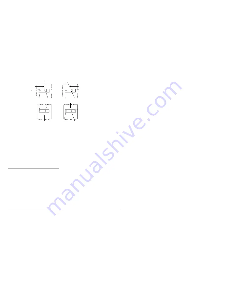
AIR FLOW
DIRECTION
DUCT
DETECTOR
HOUSING
DOTS INDICATE POSITION OF
SAMPLING TUBE HOLES
AIR FLOW
DIRECTION
DUCT
DETECTOR
HOUSING
INLET
TUBE
EXHAUST
TUBE
AIR FLOW
DIRECTION
INLET
TUBE
EXHAUST
TUBE
INLET
TUBE
EXHAUST
TUBE
DUCT
DETECTOR
HOUSING
AIR FLOW
DIRECTION
EXHAUST
TUBE
INLET
TUBE
DUCT
DETECTOR
HOUSING
A78-1812-01
Figure 4. Tube Mounting Configurations with Varying Air Flow Direction and Orientation of Detector Housing.
Vertical as well as Horizontal Mounting is Acceptable.
A. INSTALLATION FOR DUCTS LESS THAN 8 FEET WIDE
1.
If the inlet tube is longer than the width of the air duct, drill a 3/4-inch hole in the duct directly opposite the hole
already cut for the inlet tube.
If the inlet tube is shorter than the width of the air duct, install the end cap into the inlet tube (see Figure 3).
2. Slide the inlet tube into the right housing bushing. Position the tube so that the arrows point into the air flow.
3. Secure the tube flange to the housing bushing with the two #6 self-tapping screws.
4. For tubes longer than the width of the air duct, the tube should extend out of the opposite side of the duct. If there
are more than 2 holes in the section of the tube extending out of the duct, select a different tube length using Table
1. Otherwise, trim the end of the tube protruding through the duct so that 1 to 2 inches of the tube extends outside
the duct. Plug this end with the tube end plug and tape closed any holes in the protruding section of the tube. Be
sure to seal the duct when the tube protrudes.
5. Any inlet tube over 3 feet long must be supported on the opposite side of the duct detector housing.
WARNING: There must be a minimum of 10 holes in the tube exposed to the air stream.
B. INSTALLATION FOR DUCTS MORE THAN 8 FEET WIDE
NOTE: To install inlet tubes in ducts more than 8 feet wide, work must be performed inside the air duct. Sampling of
air in ducts wider than 8 feet is accomplished by using the ST-10 inlet sampling tube.
Install the inlet tube as follows:
1. Drill a 3/4-inch hole in the duct directly opposite the hole already drilled for the inlet tube.
2. Slide the inlet tube with the flange into the right housing bushing. Position the tube so that the arrows point into
the air flow. Secure the tube flange to the housing bushing with the two #6 self-tapping screws.
3. From inside the duct, couple the other section of the inlet tube to the section already installed using the 1/2-inch
conduit fitting supplied. Make sure the holes on both of the air inlet tubes are lined up facing the air flow.
4. Trim the end of the tube protruding through the duct so that 1 to 2 inches of the tube extends outside the duct. Plug
this end with the tube end cap and tape closed any holes in the protruding section of the tube. Be sure to seal the
duct when the tube protrudes.
5. Any tube (over 3 feet long) that doesn’t protrude through the duct (on the side opposite the housing) must be
supported by other means.
NOTE: An alternate method to using the ST-10 is to use two ST-5 inlet tubes. Remove the flange from one of the tubes
and install as described above. After the installation, use electrician’s tape to close off some of the sampling
holes so that there are a total of 12 holes spaced as evenly as possible across the width of the duct.
Recommended Detector Maintenance Procedure
NOTE: Notify the proper authorities that the smoke detector system is undergoing maintenance, and therefore the
system will temporarily be out of service. Disable the zone or system undergoing maintenance to prevent
unwanted alarms and possible dispatch of the fire department.
1.
Turn off power to the system.
2.
Remove and inspect sampling tube filters.
3.
If filters are heavily coated with dirt, replace them with new filters. If they are not heavily coated, use a vacuum
cleaner or compressed air nozzle to remove dust, then reinstall the filters.
4.
Remove detector from housing. (See Figure 8.)
PHOTOELECTRONIC UNITS
5.
Remove detector cover by inserting a small blade screwdriver into the slot located 90 degrees from the MOD400
test jack receptacle, twisting the cover counterclockwise to remove (see Figure 10).
6.
Lift screen from photo chamber. Vacuum screen and cover before using clean, compressed air to loosen and
blow out any remaining debris. (Replacement screens are available, part no. RS24.)
7.
Vacuum photo chamber, then use clean compressed air to blow area clean.
8.
Replace screen by aligning arrow on top with the field test slot on the base of the detector. Push screen into place.
Screen should fit tightly to chamber.
IONIZATION UNITS
9.
Remove the detector cover and screen assembly by depressing the three lock prongs on the top of the cover
and rotating the cover counterclockwise. The CRT400 Cover Removal Tool makes cover removal easier. (See
Figure 11.)
10.
Carefully pull the screen out of the cover.
11.
Clean the screen thoroughly with a soft brush or vacuum (replacement screen available, part no. RS14).
12.
Brush or vacuum the inside of the cover. Cover may then be blown out using clean, compressed air.
13.
Vacuum the sensing chamber before using clean, compressed air to loosen and blow out any remaining debris.
14.
Press the screen back into the cover.
15.
Replace the detector cover and screen assembly on the sensing chamber. Rotate it clockwise to lock it into place.
BOTH TYPES OF UNITS
16.
Reinstall the detector housing.
17.
Restore power to the system.
18.
Put detector into alarm using appropriate method described in STEP 7. PERFORM DETECTOR CHECK (page
7 of this manual).
19.
Notify the proper authorities that testing has been completed and the smoke detector system is again
operational.
20.
Other checks that should be made during maintenance procedures:
–Holes or cracks in duct work near vicinity of detector
–Air leaks where detector housing or sampling tubes are attached to duct
–Dust accumulations in or on sampling tubes
N500-04-00
4
I56-507-06
N500-04-00
9
I56-507-06


