


pressed air to blow it clean.
8. Replace the screen by aligning the arrow on top with the
field test slot on the base of the detector. Press the
screen into place. It should fit tightly into the chamber.
ION UNITS
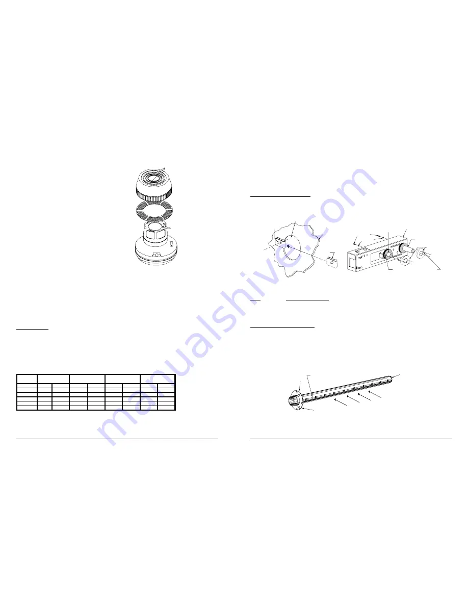
9. See Figure 11. Remove the detector cover and screen
assembly by depressing the three lock prongs on the
top of the cover and rotating the cover counterclock-
wise. The CRT400 Cover Removal Tool makes cover
removal easier.
10.Carefully pull the screen out of the cover.
11.Clean the screen thoroughly with a soft brush or vacuum.
(Replacement screens, part no. RS14.)
12.Brush or vacuum the inside of the cover. Cover may
then be blown out using clean, compressed air.
13.Vacuum the sensing chamber before using clean, com-
pressed air to loosen and blow out any remaining
debris.
14.Press the screen back into the cover.
15.Replace the detector cover and screen assembly on the
sensing chamber. Rotate it clockwise to lock it into
place.
BOTH TYPES OF UNITS
16.Reinstall the detector in its housing.
HOUSING
LOCK PRONGS
REMOVABLE SCREEN
(P/N RS14)
REMOVABLE
COVER
FOR
CLEANING
HEAD COVER
LOCK PRONGS
(A78-1812-07)
Figure 11. Ion Head Exploded View
Location of detectors mounted in or on air ducts should be at least six duct widths downstream from any duct openings,
deflection plates, sharp bends, or branch connections.
Exception: Where it is physically impossible to locate the detector accordingly, the detector can be positioned closer
than six duct widths, but as far as possible from the opening, bend, or deflection plates.
STEP 3. MOUNT DUCT HOUSING
Remove the duct housing cover. Slide the foam gaskets over the tube bushings as shown in Figure 2A. Make sure
the two small holes in the gaskets line up with the two duct housing mounting holes. Put one 5/16-inch O-ring over
each of the two #10 sheet metal screws. Use the two sheet metal screws to secure the duct housing to the duct.
CAUTION: Do not overtighten the screws.
HOLE B
HOLE A
DUCT
WALL
SPEED
NUT
SCREW HOLES FOR ATTACHING
DETECTOR HOUSING TO DUCT
FOAM GASKETS
EXHAUST TUBE
(EXTENSION BUSHING)
DUCT DETECTOR
HOUSING
O-RINGS
MOUNTING
SCREWS
INLET SAMPLING
TUBE BUSHING
A78-2046-00
A78-2045-00
Figure 2. Speed Nut Mounting Location.
Figure 2A. Installation of Foam Gaskets Over
Sampling Tube Bushings.
TABLE 1. SAMPLING (INLET) TUBES
TUBE
OUTSIDE DUCT WIDTH
ST-1.5
1 to 2 ft.
(0.3 to 0.6 m)
ST-3
2 to 4 ft.
(0.6 to 1.2 m)
ST-5
4 to 8 ft.
(1.2 to 2.4 m)
ST-10
8 to 12 ft.
(2.4 to 3.7 m)
STEP 4. INSTALL THE INLET TUBE
The inlet tube (shown in Figure 3) is identified by a series of air inlet holes on the tube. This tube must be purchased
separately. Order the correct length, as specified in Table 1, for the width of the duct where it will be installed. The
exhaust tube is molded into the base of the duct housing.
The inlet tube should be installed in the inlet sampling tube bushing located in the center of the duct detector housing.
See Figure 2A. The air inlet holes must face into the air flow. To assure proper installation, the tube mounting flange
is marked with arrows. Mount the inlet tube so that the arrows point into the air flow. Figure 4 shows the various
combinations of duct detector and tube mounting configurations with respect to air flow.
INLET
TUBE
END
PLUG
AIR HOLES
ARROWS
MUST FACE
INTO AIR FLOW
AIR FLOW DIRECTION
FLANGE
A78-2047-01
Figure 3. Air Duct Detector Inlet Sampling Tube.
17.Restore system power.
18.Put detector into alarm using appropriate method described in STEP 7. PERFORM DETECTOR CHECK.
19.Notify the proper authorities that testing has been completed and the smoke detector system is back in operation.
20.Other checks that should be made during maintenance procedures:
— Holes or cracks in duct work near the detector.
— Air leaks where detector housing or sampling tubes are attached to duct.
— Dust accumulations in or on sampling tubes.
— Wiring terminal screw tightness.
SPECIFICATIONS
Length:
14.5 inches
(36.7 cm.)
Width:
5 inches
(12.7 cm.)
Depth:
4 inches
(10.2 cm.)
Weight:
4 lbs.
(1.8 kg.)
Operating Temperature Range: 32
°
to 120
°
F
(0
°
to 49
°
C)
Operating Humidity Range:
10% to 93% Relative Humidity
Duct Air Velocity:
500 – 4000 ft./min. (91.4 – 1219.2 m/min.)
Power Supply Electrical Ratings For DHX-501
Power
120 VAC (102 - 132)
240 VAC (204 - 264)
24 VAC (20.6 - 26.4)
24 VDC (20 - 30)
Requirements
mA rms MAX.
mA rms MAX.
mA rms MAX.
mA DC MAX.
Device
Standby
Alarm
Standby
Alarm
Standby
Alarm
Standby
Alarm
DHX-501A
44
52
25
30
65
182
26
87
PA400*
--
3
--
1.5
--
29
--
15
RA400ZA*
--
1.5
--
1
--
17.3
--
10
RTS451/RTS451KEY*
--
1.5
--
1
--
17.3
--
10
RTS451**/RTS451KEY
11.5
13
5.5
6.5
140
157
95
103
* All accessory currents are additional to DHX-501. There are no additional currents for accessories in standby.
** RTS451/RTS451KEY when the magnet is held in place to initiate an alarm.
Maximum auxiliary power output current is 80 mA (terminals 3 and 6).
N500-03-00
3
I56-456-07
N500-03-00
10
I56-456-07