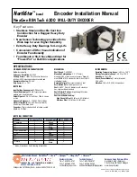
background image

Page 8

DIMENSIONS

inch

[mm]

NEMA C-FACE

4.3 [109]

3.5 [85]

8.2

[208]

12.7

[323]

SECOND OUTPUT

(OPTIONAL)

1/2" NPT

CONDUIT CONNECTION

4 SLOTS

.90X.34

[22.86X8.64]

5.0

[127]

3.0 [76]

0.9 [23]

0.16 [4]

X1.6

.19

[5X41]

ø.625 [15.88]

2.0 [51]

6.9 [175]

8.5

[216]

4 HOLES

3/8X16 UNC

ON 5.875 BC

 .625 [15.88]

0.40 [10.16]

4.5 [114]

4.2

[107]

6.2

[157]

Ordering Information

To order, complete the model number with code numbers from the table below:

Code 5: Electrical

1

One sensor
module  5-26VDC
Line driver output

2

Two sensor
modules  5-26VDC
Line Driver Output

Ordering Information

Code 2: PPR

Code 1: Model

RT6

RT6   

Foot

Mount
or Close
Coupled
Housing

0060
0064
0075
0120
0128
0150
0240
0256
0300

Code 4: Shaft

A   

Single Shaft

Stainless Steel 5/8"

B    

Dual Shaft

Stainless Steel 5/8"

S  

 Single Shaft Hi-

strength Steel 5/8"

D

     Dual Shaft Hi-

Strength Steel 5/8"

Code 3: Index

L

     No Index

Z

     With

Index Signal
Output

Code 6: Termination

C

Latching Industrial
Connector

M

10 pin MS
Connector

P

18" Long Pigtail
Cable

Q

Latching Industrial
Connector On 18"
Cable

Code 7: Options

Blank  

No Option

GB   

Shaft Grounding

Brush

(Code 

4

 must be

 S 

)

Note:

 See ACCESSORIES Section For Connectors, Spare Parts and Pulse Wheels

0480
0512
0600
0960
1024
1200
1920
2048
2400

Summary of Contents for NexGen RIM Tach 6200

Page 1: ...unted end Quadrature Phasing 90 45 Duty Cycle 50 15 ELECTRICAL Input Voltage Requirement 5 26 Volts DC Current Requirement 95 mA typical per sensor module plus line driver load Output Signals 5 26 V Line Driver 150mA source or sink Frequency Response 0 180kHz Data Index Electrical Immunity 2kV ESD Reverse Polarity Short Circuit Powered Short Connector 10 pin industrial duty latching sealed NEMA 4 ...

Page 2: ...lowing general guide lines will help to ensure a trouble free installation Mounting the Encoder Do not shock the encoder Do not subject the encoder to axial or radial shaft stresses Do not tool the encoder or its shaft Do not use makeshift techniques to mount the encoder Do not use a rigid coupling Do not disassemble the encoder Wiring the Encoder Never connect or disconnect the encoder connec tor...

Page 3: ...ut LED STATUS LIGHT A multicolor LED Status light will indicate to the user the overall condition of the encoder The LED is built into the encoder and does not require any additional wiring or power to activate it There are 4 basic status conditions for the light 1 LED off No power to Encoder Low supply voltage 3 0VDC Total Failure of Encoder 2 LED Green Correct Power to Encoder Ready to operate N...

Page 4: ...od Sensor Module 2 0 Preparation The RT 6200 utilizes a modular construction that permits the user to configure the unit as a one or two signal output tachometer Sensor modules are universal and interchangeable If one output requires replacement simply remove four screws and replace with a new sensor module No electrical adjustment or alignment is required After unpacking the unit and verifying re...

Page 5: ...m of the Model 6200 The bolt hole pattern in slotted to permit a measure of adjustment Flexible couplings are generally used to couple the Model 6200 to its driver NorthStar part number RIMFLEX 5858 There are a wide variety of speeds loads environ ment and alignment conditions found in various applications If there is doubt to suitability we recommend you consult the flexible coupling manufacturer...

Page 6: ...e perform the following steps See Figure below 1 Remove sensor module and mating connector from packaging CAUTION Although the device is protected from Electrostatic Discharges up to 2000 Volts standard ESD precautions should be followed 2 Separate mating connector from sensor module by releasing the two latches CAUTION Use caution when handling the sensor module The sensor at the end of the modul...

Page 7: ...on pages 2 3 prior to wiring the encoder 5 1 Quick Release Connector Hood Wiring To install the Quick Release Connector perform the following steps 1 Remove the four screws from the mating connec tor housing that hold the terminal block in place Remove terminal block from housing 2 Insert wiring through liquid tight flexible seal and mating connector housing Leave enough wire exposed to comfortabl...

Page 8: ... Line Driver Output Ordering Information Code 2 PPR Code 1 Model RT6 RT6 Foot Mount or Close Coupled Housing 0060 0064 0075 0120 0128 0150 0240 0256 0300 Code 4 Shaft A Single Shaft Stainless Steel 5 8 B Dual Shaft Stainless Steel 5 8 S Single Shaft Hi strength Steel 5 8 D Dual Shaft Hi Strength Steel 5 8 Code 3 Index L No Index Z With Index Signal Output Code 6 Termination C Latching Industrial C...

Reviews: