

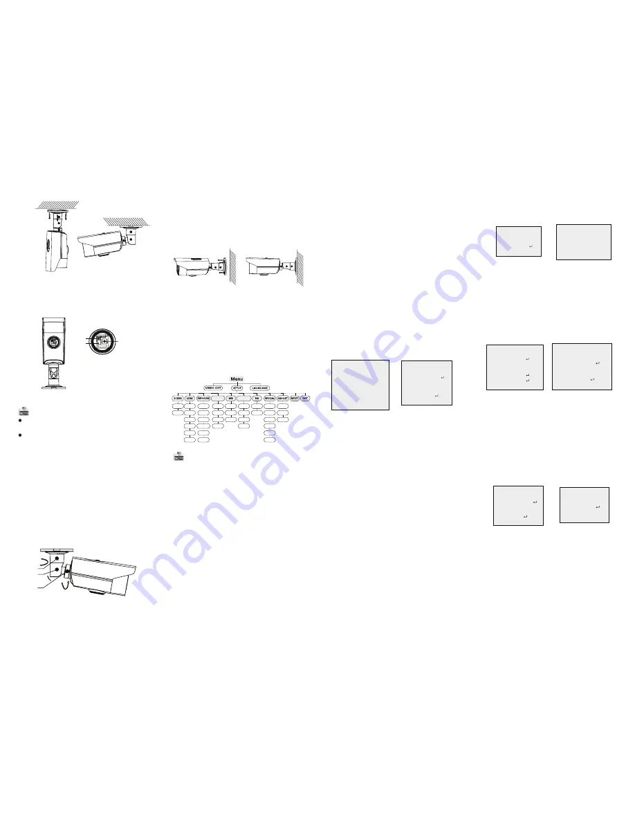
3 Menu Opera
tio
n
Figure 3-1 Main Menu
DAY&NIGHT
BACKLIGHT
INDOOR
OUTDOOR
ZOOM
SPEED
SHUTTER
AGC
SENS-UP
BRIGHTNESS
D-WDR
DEFOG
BLC
HSBLC
ATW
AWC-SET
MANUAL
COLOR
B/W
TRIGGER
2D NR
3D NR
CAM
TITLE
D-EFFECT
MOTION
PRIVACY
DEFECT
HEAT
CTRL
SHARPNESS
MONITOR
LSC
PRESET
FOCUS
MODE
LENSINIT
ZOOM
VIEW
AFLIMIT
WDR
OFF
AUTO
You can call the menu and adjust the camera
parameters with the dire
cti
on bu
tt
on or a coaxial
camera controller (purchase separately). You can
also call the menu with supported DVR.
3.1 VIDEO.OUT
PAL or NTSC is selectable .
3.2 LANGUAGE
Chinese, English & French are selectable.
3.3 SETUP
3.3.1 SCENE
You can select indoor and outdoor scene modes
according to the working environments.
3.3.3 EXPOSURE
EXPOSURE
1. EXPOSURE
IRIS-PRI
2. SHUTTER
AUTO
3. AGC
OFF
4. SENS-UP
---
5. BRIGHTNESS
---|------ 40
6. D-WDR
OFF
7. DEFOG
OFF
8. RETURN
RETURN
Figure 3-2 Exposure
EXPOSURE: Manual and IRIS-PRI are selectable.
SHUTTER: AUTO,1/25, 1/75, 1/100, 1/120…1/3.5k
, 1/6k, 1/10k, 1/20k and 1/30 kare selectable.
: You can set the AGC value from 0 to 15.
AGC
: You can set the SENS-UP to OFF or AUTO.
SENS-UP
: You can set the brightness value
BRIGHTNESS
from 1 to 14.
You can set the D-WDR as ON or OFF.
D-WDR:
: You can set the defog f
uncti
on as ON to
DEFOG
enable the
function
. P
osition
, size, and the defog
grada
ti
on are co
nfigu
rable.
3.3.4 Backlight
:
WDR Set the WDR status as ON or OFF.
Backlight
Compens
a
tio
n (BLC):
Set the gain of BLC as High, Middle, or Low.
-GAIN:
Press the up/down/le
ft/rig
ht bu
tt
on to
-AREA:
de
fin
e the BLC
positio
n and size. Select RET or
AGAIN to go back the BLC menu or re-de
fi
ne the
BLC area.
Restore the BLC se
tti
ngs to the default.
-Default:
HSBLC: Select an HSBLC area. Set the DISPLAY
status as ON. Press the up/down/le
ft/rig
ht bu
tt
on
to de
fi
ne the area posi
ti
on and size. Set the HSBLC
LEVEL from 0 to 100. Select ALL DAY or Night for the
HSBLC mode. Set the BLACK MASK status as ON or
OFF.
HSBLC
1. SELECT
AREA 1
2. DISPLAY
ON
3. LEVEL
---|------ 20
4. MODE
ALL DAY
5. BLACK MASK
ON
6. DEFAULT
7. RETURN
RETURN
Figure 3-3 HSBLC
3.3.5 White Balance (WB)
MANUAL, ATW (Auto-tracking White Balance),
AW
C→
SET are selectable.
3.3.6 Day & Night
Auto, Trigger, Color, and B/W are selectable for
DAY and NIGHT switches. You can enable IRF in
trigger mode.
3.3.7 NR
: You can set 2D NR status as ON or OFF.
2D NR
: Set the Smart NR status as ON and adjust
3D NR
the 3D smart NR sensi
ti
vity ranges from 0 to 100.
Set the 3D NR LEVEL ranges from 0 to 100. Set the
2D&3D NR
1. 2DNR
OFF
2. 3DNR
ON
3. RETURN RETURN
3D NR
1. SMART NR OFF
2. LEVEL
------|--8 0
3. START. AGC -|--------10
4. END. AGC
-|--------10
5. RETURN
RETURN
Figure 3-4 NR
Figure 3-5 3D NR
3.3.8 SPECIAL
Edit the camera
ti
tle on this se
cti
on.
Came
ra Title:
D-e
ff
ect:
Set the freeze
functio
n as ON or OFF.
-FREEZE:
OFF, MIRROR, V-FLIP, and ROTATE are
-MIRROR:
selectable for mirror.
De
fi
ne the zoom ra
ti
o of certain area
-D-ZOOM:
from 2 to 62.
Set the NEG IMAGE as ON or OFF.
-NEG.IMAGE:
SPECIAL
1. CAM TITLE
OFF
2. D-DFFECT
3. MOTION
OFF
4. PRIVACY
OFF
5. DEFECT
6. HEATCTRL
7. RETURN
RETURN
Figure 3-6 Special
MOTION
1. SELECT
AREA 1
2. DISPLAY
ON
3. SENSITIVITY
----|---- 30
4. MOTION VIEW ON
5. DEFAULT
6. RETURN
RETURN
Figure 3-7 M
oti
on Dete
cti
on
M
otio
n: Select a MOTION area. Set the DISPLAY
status as ON or OFF. Press the up/down/le
ft/rig
ht
bu
tt
on to de
fi
ne the posi
ti
on and size of the area.
Set the SENSITIVITY from 0 to 100. Set the
MOTION VIEW status as ON or OFF.
Privacy: Select a PRIVACY area. Set the DISPLAY
status as INV, MOSAIC, COLOR or OFF. Press the
up/down/le
ft/rig
ht bu
tt
on to de
fin
e the
positio
n
and size of the area. Up to 8 areas are con
fi
gurable.
Defect: LIVE DPC and STATIC DPC are selectable
in this
section
.
PRIVACY
1. SELECT
AREA 1
2. DISPLAY
MOSAIC
3. COLOR
10
4. TRANS.
1
5. DEFAULT
6. RETURN
RETURN
ADJUST
1. SHARPNESS
--------|15
2. MONITOR
LCD
3. LSC
OFF
4. RETURN
RETURN
3.3.9 ADJUST
: Adjust the sharpness from 0 to 15.
Sharpness
: Monitor CRT, and Monitor LCD are
Moni
t
o
r
selectable.
: Set the LSC status as ON or OFF.
LSC
3.3.10 RESET
Reset all the se
tti
ngs to the default.
3.3.11 EXIT
Press OK to exit the menu.
START. AGC level as the threshold to enable AGC,
and set the END. AGC level as the threshold to
disable AGC.
Figure 3-8 Privacy Mask
Figure 3-9 Adjust
3.3.2 LENS
The camera is equipped with 5-50mm motorized
vari-focal lens.
Click Zoom + and Zoom - on the DVR PTZ to zoom in
and zoom out. The camera automa
ti
cally focuses
a
ft
er zooming in/out.
Move the cursor le
ft
/right to adjust
ZOOM SPEED:
the zoom speed.
PRESET: You can set, delete, and call the preset. 1
to 64 presets are co
nfigu
rable.
Figure 2-2 Fix the Camera to the Ceiling
Figure 2-4 3-axis Adjustment
Figure 2-5 Fix the Camera to the Wall
5.Rotate the cover of camera an
ti
clockwise and the
dire
ctio
n bu
tt
on, auxiliary video interface, and
the DIP switch show.
1
2
3
1.Directi
on Bu
tto
n
2.Auxiliary Video Output
3.DIP Switch
Figure 2-3 Image Adjustment
A small monitor can be connected to the auxiliary
video output to adjust the video.
DIP switch is used to enable/disable WDR
functi
on.
(By disabling WDR
functi
on, video output can be
realized by both CVBS output and HD video output.)
(By enabling WDR
function
, video output cannot be
realized by CVBS output.)
2
1
360°
3
90°
360°
6. Adjust the surveillance angle.
1). Loosen No.1 adjus
tin
g screw to adjust the pan
positio
n (0 ~ 360 ).
°
°
2). Loosen No.2 adjus
tin
g screw to adjust the
tiltin
g
position(
0 ~ 90 ).
°
°
3). Loosen No.3 adjus
tin
g screw to adjust the
rota
tio
n
positio
n 0 ~ 360 .
( °
° )
4).Tighten the adjus
tin
g screws
.
2.2 Wall
Mou
n
tin
g
Steps:
1.Drill the screw holes and the cable hole in the
ceiling according to the supplied drill template.
2.Hammer the supplied plas
ti
c expansion bolt into
the screw holes.
3.Route the cables to the cable hole and connect
the corresponding cables.
4.Fix the camera to the ceiling with the supplied
PA4 screws.
5.Adjust the surveillance angle as shown in the
fi
gure 2-4.
FOCUS MODE: Manual, Auto, and Trigger modes
are selectable. In auto mode, the camera focuses
automa
ti
cally, and in manual mode, you can click
Zoom+ and Zoom- to focus.
You can reset the lens.
LENSINIT:
AFLIMIT: 20m, 10m, 6m, 3m, 1.5m, 1m, 30cm, and
10cm are selectable as the Min. focus distance limit.
Enable the zoom view and the zoom
ZOOM VIEW:
ra
ti
o displays while lens zooming in/out.
HEAT CTRL: AUTO, ON and OFF are selectable in
this
section
.


