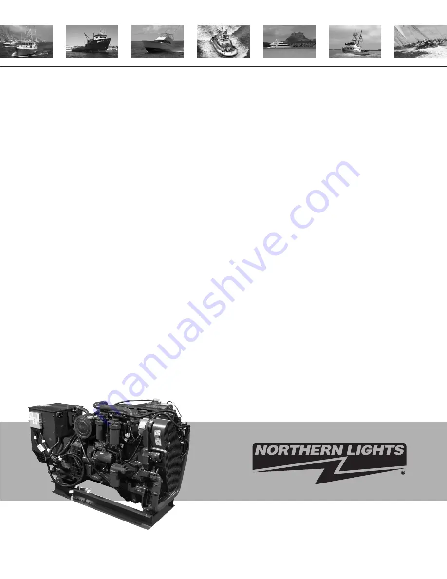
OM-C3
For Models: M50C13, M80C13, M65C13,
M99C13, M120C13 and M150C13
OPERATOR’S MANUAL
www.northern-lights.com
Page 1: ...OM C3 For Models M50C13 M80C13 M65C13 M99C13 M120C13 and M150C13 OPERATOR S MANUAL OPERATOR S MANUAL www northern lights com...
Page 2: ...21 Breathing Diesel engine exhaust and some of its constituents are known to the State of California to cause cancer birth defects and other reproductive harm Always start and operate the engine in a...
Page 3: ...Storing Diesel Fuels 21 Biodiesel Fuel 22 24 Oil and Filter Service Intervals 24 Lubricant Storage 24 Oil Filters 24 COOLANT Engine Coolants 25 Water Quality for Mixing with Coolant Concentrates 25 F...
Page 4: ...number please refer only to the number stamped on the Northern Lights serial number plate 50 kW Northern Lights commercial marine generator set with a John Deere Powertech Tier III 6068 engine block...
Page 5: ...d and clean condition Replace missing or damaged signs Be sure new equipment components and repair parts include the current safety signs For replacement signs proper placement of safety signs or clar...
Page 6: ...g parts have stopped before making any adjustments connections or performing any other type of service to the engine or other driven equipment Prevent accidental discharge of starting fluids by storin...
Page 7: ...poisonous and strong enough to burn skin eat holes into clothing and other materials and cause blindness if splashed into eyes To Avoid Hazards Fill batteries only in well ventilated areas Wear appro...
Page 8: ...of paint and solvent properly Service Cooling System Safely WARNING Opening a pressurized cooling system can release explosive fluids and causing serious burns Before opening any pressurized cooling s...
Page 9: ...r grinding materials containing asbestos When servicing wear an approved respirator A special vacuum cleaner is recommended to clean asbestos If this vacuum is not available apply a mist of oil or wat...
Page 10: ...cannot be achieved at the local supply valve shut off valves further back in the system and re check the bleed off point until complete shut off is achieved Affix a DO NOT OPERATE tag to each valve ha...
Page 11: ...OM C3 11 21 9 Notes...
Page 12: ...olant Fill 6 Alternator 7 Belt Guard 8 Starter 9 Lube Oil Dipstick 10 Lube Oil Filter 11 Turbocharger 12 Fuel Injection Pump 13 Exhaust Elbow 14 Thermostat Cover 15 Expansion Tank 16 Stop Start Panel...
Page 13: ...ir Cleaner 3 Coolant Fill 4 Alternator 5 Belt Guard 6 Lube Oil Dipstick 7 Lube Oil Filter 8 Lube Oil Fill 9 Fuel Filter 10 Fuel Injection Pump 11 Starter 12 Thermostat Cover 13 Expansion Tank 14 Exhau...
Page 14: ...er the engine starts release the switch and it will return to RUN position To stop the engine hold the switch in the STOP position 3 OIL PRESSURE GAUGE Shows the oil pressure in the engine lubricating...
Page 15: ...on engine Unless temperature drops quickly stop engine and determine cause before resuming operation Operate the engine under a lighter load and at slower than normal speed for first 15 minutes after...
Page 16: ...riod of time divided by the full power fuel consumption for the same period of time For example if an engine burns 160 L of fuel during an eight hour run and the full power fuel consumption is 60 L pe...
Page 17: ...3 API CF 2 API CF BREAK IN SERVICE The engine is ready for normal operation However extra care during the first 100 hours of operation will result in more satisfactory long term engine performance and...
Page 18: ...rises above maximum coolant temperature see GENERAL ENGINE SPECIFICATIONS in Specifications Section reduce load on engine Check sea raw water strainer for plugging on heat exchanger engines Unless te...
Page 19: ...engine to run extended period of time with no load AUXILIARY GEAR DRIVE LIMITATIONS IMPORTANT When attaching a sea water pump or other accessory to be driven by the auxiliary gear drive A engine timi...
Page 20: ...t for water flow Check exhaust pipe for water flow on engines with wet exhaust systems If sea water does not flow within one minute after engine starts stop engine and check sea cock sea water straine...
Page 21: ...ts may cause the terminals to erode over time and not make a good electrical connection 2 If a connector is not in use put on the proper dust cap or an appropriate seal to protect it from foreign debr...
Page 22: ...45 mm as measured by ASTM D6079 or ISO 12156 1 Diesel fuel quality and sulfur content must comply with all existing emissions regulations for the area in which the engine operates DO NOT use diesel fu...
Page 23: ...the diesel fuel used in your machine demonstrates good lubricity characteristics Fuel lubricity should pass a maximum scar diameter of 0 45 mm as measured by ASTM D6079 or ISO 12156 1 If fuel of low o...
Page 24: ...14 specification primarily available in Europe Engines operating on biodiesel blends above B20 might not fully comply with or be permitted by all applicable emissions regulations Expect up to a 12 red...
Page 25: ...ontent appearance suitability for cold weather operations bacteria cloud point acid number particulate contamination and whether the fuel meets specification Contact your Northern Lights dealer for mo...
Page 26: ...t engine oil and filter service intervals Higher fuel sulfur levels reduce oil and filter service intervals as shown in the table Use of diesel fuel with sulfur content less than 0 05 500 mg kg is str...
Page 27: ...et the following specification Pre mix coolant meeting ASTM D6210 requirements Coolant concentrate meeting ASTM D6210 requirements in a 40 60 mixture of concentrate with quality water WATER QUALITY FO...
Page 28: ...in geographical areas where freeze protection is not required IMPORTANT Water may be used as coolant in emergency situations only Foaming hot surface aluminum and iron corrosion scaling and cavitatio...
Page 29: ...place primary air cleaner element when restriction indicator shows a vacuum of 625 mm 52 in H20 or when reset button has popped up 2 Change the oil for the first time before 100 hours maximum of break...
Page 30: ...l may be added at rocker arm filler cap C SP1 Check engine oil level Check engine oil level on dipstick A Add as required using seasonal viscosity grade oil See DIESEL ENGINE OIL in Fuels Lubricants a...
Page 31: ...d be opened to ensure that no air pockets form in the cooling system SP3 Check seawater strainer IMPORTANT A restricted or clogged sea water strainer will result in hotter than normal or overheated en...
Page 32: ...ke a thorough inspection of the engine room Look for oil or coolant leaks worn drive belts loose connections and trash build up Remove trash buildup and have repairs made as needed if leaks are found...
Page 33: ...andard filters 8 Tighten drain plug to the following specifications Oil Pan Drain Plug with Copper Washer Torque 70 N m 52 lb ft Oil Pan Drain Plug with O Ring Torque 50 N m 37 lb ft continued on next...
Page 34: ...oil To determine the correct oil fill quantity for your engine see ENGINE CRANKCASE OIL FILL QUANTITIES in the Specifications Section of this manual NOTE Crankcase oil capacity may vary slightly ALWAY...
Page 35: ...rd Duty Starter Cold Cranking Amps 570 Service and Maintenance 250 Hour CAUTION SP9 Service Battery WARNING Battery gas is highly flammable Battery explosions can cause severe injury or death To help...
Page 36: ...kes apart when tapped install a new zinc plug 3 Measure zinc plugs A to determine the amount of erosion on length B and outer diameter C Location of zinc plugs A and end cap B M150C13 If length is les...
Page 37: ...oses A B and C upper right and oil drain line D below right for kinks blockage or other damage 2 Inspect crankcase fitting E below right for damage and make sure it is not plugged 3 Verify that the cr...
Page 38: ...e Whenever the fuel system has been opened up for service lines disconnected or filters removed it will be necessary to bleed air from the system See BLEEDING THE FUEL SYSTEM on Page 63 CAUTION Locati...
Page 39: ...ter water separator D M50C13 M65C13 M99C13 Location of electrical connector A drain B filter base C filter water separator D M150C13 NOTE Raised locators on fuel filter canister must be indexed proper...
Page 40: ...tensioner assembly Checking Belt Wear The belt tensioner is designed to operate within the limit of arm movement provided by the cast stops A and B below when correct belt length and geometry is used...
Page 41: ...ys or bearings need replacement contact your Northern Lights dealer 2 Release tension on tension arm and remove drive tool 3 Put a mark A right on swing arm of tensioner as shown 4 Measure 21 mm 0 83...
Page 42: ...n DO NOT mix one brand of SCA with a different brand Test the coolant solution at 500 hours or 12 months of operation using either coolant test strips or a COOLSCAN or COOLSCAN PLUS analysis If a COOL...
Page 43: ...en either end cap is removed It is strongly recommended that both end caps be removed for cleaning when cleaning the heat exchanger core 5 Remove remaining end cap from water manifold heat exchanger h...
Page 44: ...6 4 mm 0 25 in from housing C Index end cap in same position as removed 2 Install heat exchanger core Make sure core is properly seated in rear end cap to avoid cutting O ring 3 Install front end cap...
Page 45: ...cap and O ring 5 Remove clamps E right and remove hoses from front cap 6 Remove four cap screws F right front cap and O ring 7 Remove aftercooler core from the rear of the engine 8 Thoroughly clean a...
Page 46: ...first measurement was accurate Test Cooling System NOTE Engine should be warmed up to test overall cooling system 1 Allow engine to cool then carefully remove coolant filler cap 2 Fill tank with cool...
Page 47: ...onnections clean and tight to prevent electrical arcing which can damage electronic components SP 22 Flushing and Refilling Cooling System Explosive release of fluids from pressurized cooling system c...
Page 48: ...der is at TDC compression stroke Insert Timing Pin in flywheel If No 1 cylinder rocker arms are loose the engine is at No 1 TDC compression If No 1 cylinder rocker arms are not loose rotate engine one...
Page 49: ...1 5 3 6 2 4 Lock No 1 piston at TDC compression stroke B right Adjust valve clearance on No 1 3 and 5 exhaust valves and No 1 2 and 4 intake valves Rotate flywheel 360 Lock No 6 piston at TDC compres...
Page 50: ...ld be replaced IMPORTANT The vibration damper assembly is not repairable Replace damper every 4500 hours or 60 months whichever occurs first 3 Check vibration damper radial runout by positioning a dia...
Page 51: ...ng G and exhaust manifold 4 Remove cap screws F attaching thermostat housing to the exhaust manifold 5 Remove thermostat housing with gasket I Remove and discard all gasket material Clean all sealing...
Page 52: ...ng water Either may rupture if overheated 4 Suspend thermostats and a thermometer in a container of water 5 Stir the water as it heats Observe opening action of thermostat and compare temperatures wit...
Page 53: ...can cause the impeller to swell and are not recommended to free a stuck impeller 3 Carefully remove impeller with cam plate Be careful not to damage impeller if in reusable condition Remove key from...
Page 54: ...missing Impellers that are run dry will over heat and fail the impeller blades at the root Impellers that swell and stick fail the impeller in the middle of the blade If impeller replacement is neces...
Page 55: ...aft C is free from splined drive gear ID D 4 Clean all gasket material from both mating surfaces Install Sea Water Pump 1 Position a new gasket on water pump mounting flange Install splined pump shaft...
Page 56: ...g key C to the pump shaft keyway 5 Install lock washer E and hex nut F finger tight and insure key is properly in place 6 Tighten hex nut to 68 N m 50 lb ft 7 Install sea water pump with new gasket to...
Page 57: ...defects Replace O ring G if necessary 5 Install sea water pump with O ring on studs F Install nuts E finger tight evenly on both studs and tighten to 60 N m 44 lb ft 6 Install bracket cap screws D and...
Page 58: ...IMPORTANT Petroleum based lubricants can cause the impeller to swell and are not recommended to lubricate the impeller before installation 2 Lubricate impeller blades with a non petroleum based lubri...
Page 59: ...en coolant is added 1 Loosen temperature sending unit fitting at rear of cylinder head or plug in side of thermostat housing to allow air to escape when filling system IMPORTANT When adding coolant to...
Page 60: ...for replacement instructions 2 Tap end of filter GENTLY on hard surface to dislodge loose dirt 3 Brush dirt side of filter GENTLY with soft bristle brush IMPORTANT DO NOT clean element with gasoline s...
Page 61: ...r put filter in service without oiling it The filter will not function properly without oil Do not use automatic transmission fluid motor oil diesel fuel or any type light weight spray lubricant These...
Page 62: ...restriction indicator A shows vacuum of 625 mm 25 in H2O or when reset button has popped up if equipped Also replace element if it is torn or visibly dirty 1 Release air filter assembly clamps A and...
Page 63: ...hern Lights dealer 1 Remove cap screws A and carefully remove belt guard from engine 2 Release tension on belt using a breaker bar and socket on tension arm and remove poly vee belt from pulleys 3 Ins...
Page 64: ...iece of cardboard Protect hands and body from high pressure fluids If an accident occurs see a doctor immediately Any fluid injected into the skin must be surgically removed within a few hours or gang...
Page 65: ...11 Low Pressure Fuel Pump Connector 12 Oil Pressure Sensor Connector 13 Fuel Pressure Sensor Connector 14 Water in Fuel Sensor Connector 15 Fuel Rail Pressure Sensor Connector 16 Crankshaft Position...
Page 66: ...ntive oil to the engine crankcase for every quart of oil This rust preventive oil should be an SAE 10 oil with 1 4 percent morpholine or equivalent vapor corrosion inhibitor 2 Ensure the machine fuel...
Page 67: ...r poly vee belt if removed Adjust belt tension See CHECKING BELT TENSIONER SPRING TENSION AND BELT WEAR pages 38 39 Install belt guard 4 Perform all appropriate pre starting checks See DAILY PRESTARTI...
Page 68: ...fuel line Cold weather Slow starter speed Crankcase oil too heavy Improper type of fuel Water dirt or air in fuel system Clogged fuel filter Dirty or faulty injection nozzles Electronic fuel system pr...
Page 69: ...ance Dirty or faulty injection nozzles Injector tip deposits Injection pump out of time Turbocharger not functioning Turbocharged engines only Add oil to engine crankcase Consult Authorized Dealer Rem...
Page 70: ...me Improper type of fuel Clogged or dirty air cleaner Engine overloaded Fuel injectors dirty Consult Authorized Dealer Consult Authorized Dealer Clean or replace fuel hose Consult Authorized Dealer Ha...
Page 71: ...proper valve clearance Injection nozzles dirty Injector tip deposits Consult Authorized Dealer Consult Authorized Dealer Consult Authorized Dealer Reduce load Fill coolant tank to proper level Check c...
Page 72: ...uipped units only Marine gear control engaged Loose or corroded connections Low battery output voltage Faulty start circuit relay Blown main system fuse Consult Authorized Dealer Consult Authorized De...
Page 73: ...Low battery output Crankcase oil too heavy Loose or corroded connections Blown fuse on magnetic switch Faulty battery connection Sulfated or worn out batteries Blown main system fuse Consult Authorize...
Page 74: ...qt 15 16 15 16 15 16 Cooling System Liquid pressurized with centrifugal pump Recommended Pressure Cap kPa psi 110 16 110 16 Coolant Temperature Operating Range C F 82 94 180 202 82 94 180 202 82 94 1...
Page 75: ...qt 15 16 18 19 18 19 Cooling System Liquid pressurized with centrifugal pump Recommended Pressure Cap kPa psi 110 16 110 16 110 16 Coolant Temperature Operating Range C F 82 94 180 202 82 94 180 202...
Page 76: ...74 OM C3 11 21 AC Wiring Diagram Updated 11 17 21 Northern Lights AC Wiring Diagram M99C3 12 wire Stamford UCI w SX460 Drawing B 11997 Drawings subject to change without notice...
Page 77: ...OM C3 11 21 75 AC Wiring Diagram Northern Lights AC Wiring Diagram M99C13 12 wire Stamford UCI w PMG MX341 Drawing B 10181B Drawings subject to change without notice Updated 11 17 21...
Page 78: ...76 OM C3 11 21 DC Wiring Diagram DC Wiring Diagram Run Start Switches M50C13 M55C13 M65C13 D 4666 Drawings subject to change without notice...
Page 79: ...OM C3 11 21 77 DC Wiring Diagram DC Wiring Diagram Run Start Switches M80C13 M99C13 D 4660 Drawings subject to change without notice...
Page 80: ...78 OM C3 11 21 DC Wiring Diagram DC Wiring Diagram Run Start Switches M120C13 M150C13 D 5079 Drawings subject to change without notice...
Page 81: ...OM C3 11 21 79 AC Wiring Diagram Northern Lights AC Wiring Diagram M99C13 12 wire Stamford UCI SX460 Drawing B 10180 Drawings subject to change without notice Updated 11 17 21 NON CURRENT MODEL...
Page 82: ......
Page 83: ......
Page 84: ...4420 14th Ave NW Seattle WA 98107 Tel 206 789 3880 1 800 762 0165 www northern lights com Northern Lights and Lugger are registered trademarks of Northern Lights Inc 2021 All rights reserved Litho USA...