background image

OM843NW3 5/21

15

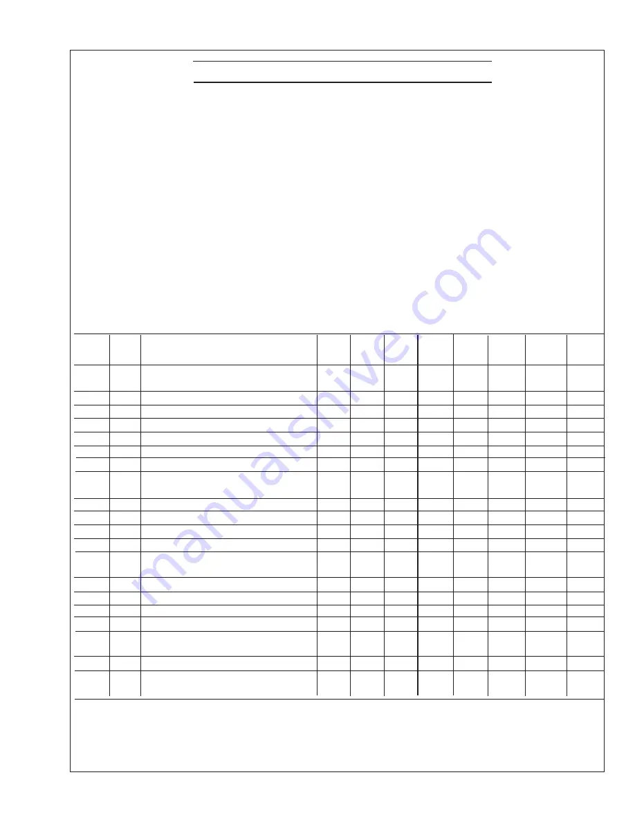
Servicing Schedule Chart

Updated 10-3-19


After 

After 

Every  Every  Every  

Every   Every


SERVICE


50 

100 100 

200 

500 1000 2500


POINT

  PAGE  OPERATION 

DAILY Hours  Hours  Hours  Hours Hours  Hours Hours


ENGINE:


SP1 16 

Check oil level 


 SP2 

16 

Change engine oil 1) 4) 


•   •

 SP3 

16


Change lube oil filters

 1) 4)  


 SP4 

17 

Check air cleaner 1)  


SP4 17 Change air cleaner 1)  


 SP5 

17 

Check V-belt tension 1) 


   SP6 

18 Check 

valve clearance 1) 2) 


FUEL SYSTEM:

 SP7 

19


Check primary filter

 (Racor) 2) 3) 


 SP8 

19


Change primary filter element

 2) 3) 


 SP9 19


Change secondary fuel filter

 1) 3) 


 SP10 

20 Check 

injectors 1) 3) 5) 


 SP11 

20 

Check fuel injection pump 6) 


COOLING SYSTEM:

  SP12 

22 

Check cooling water level 


 SP13 

22


Check and flush cooling system 


 SP14 

23 

Check and clean heat exchanger  


   SP15 

23 Change impeller in raw water pump 1) 3)  


  SP16 

23 

Check exhaust elbow 


ELECTRICAL SYSTEM:

 SP17 

24 

Check electrolyte level in batteries 1)  


 SP18 

24 

Check condition of batteries 1)  


OUT OF SERVICE:

  SP19 

24 

Winterizing or out-of-service 3)

The Servicing Schedule Chart below shows the service schedule required for proper maintenance of your generator 

set. More detailed coverage of each Service Point (SP) is listed on the page noted in the ‘page’ column.

DAILY:

 SP1 

Check oil level in engine

 SP7 

Check primary fuel filter

 SP10 

Check cooling water level


AFTER FIRST 50 HOURS:

 SP2/3 

Change engine oil and filter

AFTER FIRST 100 HOURS:

 SP2/3 

Change engine oil and filter

EVERY 100 HOURS:

 SP6

  Check v-belt tension

 SP17 

Check electrolyte level in batteries


EVERY 200 HOURS:

 SP2/3 

Change engine oil and filter

 SP4 

Check air cleaner


SP18 

Check condition of batteries

EVERY 500 HOURS:

 SP8 

Change primary fuel filter element

 SP9 

Change secondary fuel filter 

 SP15 

Change impeller in raw water pump


SP16

  Check exhaust elbow 

EVERY 1000 HOURS:

 SP5 

Change air cleaner element

 SP12 

Check injectors

EVERY 2500 HOURS:

 SP13 

Check fuel injection pump


SP11 

Check and flush cooling system

 SP14 

Check and clean heat exchanger 

1) Perform all maintenance every two years at minimum, even if hour level has 

not been reached.

2) Consult manufacturer's maintenance schedule, note on chart.

3) Whenever necessary.

4) After first 50 hours, then at 100 hours, then every 200 hours.

5) Clean injection nozzles every 1500 hours.

6) 

For EPA emission standards fuel nozzle needs to be 

cleaned every 1500 hours, the fuel nozzle and fuel pump 

need to be cleaned, adjusted, or repaired every 3000 

hours, and the quality guarantee for these parts is 1500 

hours or 2 years.

Summary of Contents for Lugger M843NW3

Page 1: ...OM843NW3 For Models M843NW3 M843NW3G OPERATOR S MANUAL OPERATOR S MANUAL www northern lights com ...

Page 2: ...to the outside Do not modify or tamper with the exhaust system Do not idle the engine except as necessary For more information go to www P65warnings ca gov diesel CALIFORNIA Proposition 65 Warning Northern Lights 4420 14th Avenue NW Seattle WA 98107 Tel 206 789 3880 Fax 206 782 5455 Copyright 2021 Northern Lights Inc All rights reserved Northern Lights and the Northern Lights logo are trademarks o...

Page 3: ...ies 1 B 12 Series 3 B 12 Series 3 C 12 OPERATING PROCEDURES Break in Period 13 Before Starting 13 Starting 13 Operating 13 Stopping 13 Shutdowns and Alarms 14 Spare Parts 14 SERVICING SCHEDULE CHART 15 SERVICING Lubrication General 16 Checking Oil Level 16 Oil Changes 16 Changing Oil Filter 16 Air Cleaner 17 V Belts 17 Valve Clearances 18 Fuels General 19 Fuel Filters 19 Injector Service 20 Inject...

Page 4: ...al service manual Nor will it make the reader into an expert mechanic Its aim is to aid you in maintaining your unit properly Northern Lights marine diesel generator set with an 843 engine and a PX 312K2 generator end US EPA Tier III M843NW3 Your set has three serial numbers 1 an engine number stamped on the block 2 a generator plate and 3 a generator set plate Use the serial number on the generat...

Page 5: ...n good and clean condition Replace missing or damaged signs Be sure new equipment components and repair parts include the current safety signs For replacement signs proper placement of safety signs or clarification on any safety issue consult your Northern Lights dealer or the factory There can be additional safety information contained on parts and components from outside suppliers that is not re...

Page 6: ...oil or debris Disconnect battery ground cable before making any adjustments or service work Handle Fuel Safely Avoid Flames WARNING Diesel is highly flammable and should be treated with care at all times Do do not refuel while smoking or when near sparks or open flame ALWAYS STOP ENGINE BEFORE FUELING MACHINE Always fill portable fuel tank outdoors Never fuel a hot engine Prevent accidental discha...

Page 7: ... open flame away from the top of battery When checking battery electrolyte level use a flashlight Safety Rules Continued Never check battery charge by contacting the posts with a metal object Use a volt meter or hydrometer Frozen batteries may explode if charged Never charge a battery that has not been allowed to warm to at least 16oC 60oF Always remove grounded battery clamp first and replace gro...

Page 8: ...ds Handle Chemical Products Safely WARNING Direct exposure to hazardous chemicals can cause serious injury Among the potentially hazardous chemicals that may be used with Northern Lights products are lubricants coolants paints and adhesives All potentially hazardous chemicals come with a Material Data Safety Sheet MSDS The MSDS provides specific details on chemical products including physical haza...

Page 9: ...o not use food or beverage containers that may mislead someone into drinking from them Do not pour waste onto the ground down a drain or into any water source Do Not Open High Pressure Fuel System DANGER Many Northern Lights engines use high pressure fuel injection High pressure fluid remaining in fuel lines can cause serious injury Do not disconnect or attempt any repair of fuel lines sensors or ...

Page 10: ... be achieved at the local supply valve shut off valves further back in the system and re check the bleed off point until complete shut off is achieved Affix a DO NOT OPERATE tag to each valve handle that requires shut off Each DO NOT OPERATE tag must be signed and dated by the authorized technician servicing the equipment Lock Out Tag Out Instructions Air Hose Connected Pneumatic Equipment Equipme...

Page 11: ...cations 16 Oil Filter 17 Oil Drain 18 Generator Set Plate 19 Control Panel Plug in 20 Fuel Lift Pump 21 Heat Exchanger End Cap 22 Coolant Fill Figure 1A and 2A M843NW3 9 Belt Guard 10 Injection Pump 11 Oil Fill 2 Places 12 Seawater Pump 13 Fresh water Block Drain behind hoses 14 Fuel Inlet Return 15 Oil Dipstick 23 Expansion Tank 24 Wet Exhaust Elbow 25 Junction Box 26 Vibration Mount 27 Starter 2...

Page 12: ...Set Plate 19 Control Panel Plug in 20 Fuel Lift Pump 21 Heat Exchanger End Cap Figure 1B service side and 2B non service side M843NW3 with 2011 Base frame 8 Fuel Injector 9 Belt Guard 10 Injection Pump 11 Oil Fill 2 Places 12 Seawater Pump 13 Fresh water Block Drain behind hoses 22 Coolant Fill 23 Expansion Tank 24 Wet Exhaust Elbow 25 Junction Box 26 Vibration Mount 27 Starter 28 DC Alternator Ma...

Page 13: ... 18 Generator Set Plate 19 Control Panel Plug in 20 Starter 7 Oil Fill top 8 Fuel Injector 9 Crankcase Vent 10 Belt Guard 11 Injection Pump 12 Fuel Lift Pump 13 Oil Fill side 21 DC Alternator 22 Heat Exchanger End Cap 23 Coolant Fill 24 Expansion Tank 25 Wet Exhaust Elbow 26 Junction Box 27 Vibration Mount Figure 1C service side and 2C non service side M843NW3G Gem Series s n 8432 54693 and above ...

Page 14: ...n To stop the engine hold the switch in the STOP position NOTE The rocker switch is used on Series 1 panels only and has a light that glows when the set is running 3 HOUR METER Keeps track of engine running time 4 OIL PRESSURE GAUGE Shows the oil pressure in the engine lubricating system 5 WATER TEMPERATURE GAUGE Registers the temperature of the cooling water 6 D C VOLTMETER OR AMMETER When the en...

Page 15: ...ngine Holding the switch too long can burn out the glow plugs This step is not necessary if the engine is already warm 2 While holding the Shutdown Bypass Preheat switch in the ON position push the Engine Control switch to the START position 3 As soon as the engine starts release the start switch and continue to hold the bypass preheat switch for an additional five seconds Do not crank the starter...

Page 16: ...pump impeller b Check the engine crankcase oil level c If the oil level is low fill with recommended lubricating oil and restart Watch the oil pressure gauge carefully and shut off the engine if it does not show a normal reading 20 60 PSI after a few seconds of operation d If the oil level is normal DO NOT restart the engine Call your dealer for assistance SPARE PARTS 1 Northern Lights recommends ...

Page 17: ...ach Service Point SP is listed on the page noted in the page column DAILY SP1 Check oil level in engine SP7 Check primary fuel filter SP10 Check cooling water level AFTER FIRST 50 HOURS SP2 3 Change engine oil and filter AFTER FIRST 100 HOURS SP2 3 Change engine oil and filter EVERY 100 HOURS SP6 Check v belt tension SP17 Check electrolyte level in batteries EVERY 200 HOURS SP2 3 Change engine oil...

Page 18: ...termittent cold weather operation change oil every 100 hours or six weeks whichever comes first 4 Change oil at the end of each season and the beginning of each season 5 Change oil when engine is warm 6 Dispose of waste oil in an approved manner 7 Never use a flushing oil 8 Loosen the clamp on the oil change tube Remove cap Drain oil Replace the cap and tube 9 Refill engine with recommended oil fo...

Page 19: ...er at recom mended times can cause severe engine damage Change every 1000 hours or two years whichever comes first NOTE Make absolutely sure no impurities enter the engine while changing the element Do NOT run the engine with the air cleaner removed SP 5 V BELTS 1 Check the tension and wear on the V belt daily 2 Use your thumb to press on the belt at the midpoint between the crankshaft and alterna...

Page 20: ...top mark of the crank pulley with the top mark of the timing gear case 3 Loosen the lock nut and adjust the clearance between the rocker arm and valve guide of both the intake and exhaust valves with the adjustment screw Figure 7 Clearance on both intake and exhaust valves should be 0 008 in 0 2 mm 4 Repeat steps 3 and 4 for each cylinder Each set of valves must be adjusted individually 5 Replace ...

Page 21: ...ll reduce condensation FUEL FILTERS 1 Your generator set should have a primary fuel filter installed We recommend the Racor brand of fuel filter water separators SP 7 PRIMARY FUEL FILTER a Check the primary fuel filter daily as recommended by the filter manufacturer Empty the collection bowl as necessary SP 8 PRIMARY FUEL FILTER ELEMENT b Change the element as often as necessary or every 500 hours...

Page 22: ...all a new copper sealing washer in each injector hole Figure 17 b Screw in injector and tighten to 43 or 50 ft lbs 6 to 7 kgm Figure 18 NOTE Overtightening can damage injector c Install return line using new copper sealing above and below each connection Tighten return line retaining bolts to 22 30 ft lbs d Install delivery lines Leave loose at injectors for bleeding e Pump hand level on fuel pump...

Page 23: ...ver lines inlets and injection pump outlets Figure 14 Remove return line Figure 15 Unscrew injector Figure 16 Remove and replace copper sealing washer Figure 17 Reinstall injector Torque to proper tightness Figure 13 Remove return line nuts For illustrative purposes only may not be your exact model Updated 10 3 19 ...

Page 24: ...the level should be about 1 in 2 5 cm below the filler cap sealing surface when the engine is cold 2 The pressure valve in the filler cap releases when the pressure is approximately 7 PSI 0 5 bar Use a cap pressure tester to check cap if you suspect it is faulty SP 13 COOLING SYSTEM FLUSHING 1 Flush the cooling system every 2500 hours or every 24 months whichever comes first a Remove expansion tan...

Page 25: ...ance and operation recommendations for the generator end are can be found in Owner s Manual OPX300K 2 included with your manual kit Contact your Authorized Northern Lights dealer or factory representative for additional copies ELECTRICAL SYSTEM GENERAL CAUTION Excessive non linear loads can lead to regulator and or generator end failures and should be no greater than 20 of overall load Failures ca...

Page 26: ...the following preparations should be taken for long term storage Change engine oil and filter as per recommendations on page 16 Run the engine up to at least 140o F from a small clean source of fuel dosed with either Stab il brand fuel system stabilizer diesel engine formula or Stanadyne Performance fuel system conditioner If neither of these fuel treatments is available you may also use John Deer...

Page 27: ... plug connection Low battery output Check specific gravity of each battery Check electrolyte level of each battery Defective electrical system Repair or replace ground wire Starter Cranks Slowly Low battery output Battery is too small Battery cables are too small Check specific gravity Replace battery if necessary of each battery Check electrolyte level If low fill cells with distilled water of ea...

Page 28: ...njection nozzles Engine Runs Irregularly Below normal engine temperature Remove and check thermostat or Stalls Frequently Clogged primary Clean or replace filter element fuel filter element Clogged secondary Replace secondary filter element fuel filter element Water or dirt in the fuel system Drain flush fill and bleed system Dirty or faulty injection nozzles Have your dealer check injection nozzl...

Page 29: ...Keel cooling tubes Remove paint from tubes have been painted marine Cooling system interior dirty Flush cooling system Defective thermostat Remove and check thermostat Defective temperature gauge Check water temperature with thermometer and replace gauge if necessary Water pump impeller worn broken Check impeller and replace if necessary V belts slipping Fix belts to proper tension Engine Knocks I...

Page 30: ... clearances Valve spring broken Replace valve spring Governor spring broken Replace governor spring Low Oil Pressure Low oil level Fill crankcase to proper level Improper type of oil Drain and fill crankcase with correct oil Partially plugged oil filter Replace filter Check bearings oil pump and relief valve for wear High Oil Consumption Break in period Oil consumption decreases after break in Cra...

Page 31: ...OM843NW3 5 21 29 AC Wiring Diagrams AC Wiring Diagram M843NW3 for 12 4 lead generators with AVR DST 100 2FAK B 9724J Updated 4 23 20 ...

Page 32: ...OM843NW3 5 21 30 AC Wiring Diagrams AC Wiring Diagram M843NW3 for 12 lead generators with AVR DST 100 2FAK B 9723H Updated 4 23 20 ...

Page 33: ...OM843NW3 5 21 31 AC Wiring Diagrams AC Wiring Diagram M843NW3 for 4 lead generators 120 240 VAC with Circuit breaker B 8399K Updated 10 13 20 ...

Page 34: ...OM843NW3 5 21 32 AC Wiring Diagrams AC Wiring Diagram M843NW3 for 4 lead generators 100 120 VAC with Circuit breaker B 10686B Updated 4 23 20 ...

Page 35: ...OM843NW3 5 21 33 DC Wiring Diagrams DC Wiring Diagram M843NW3 12 VDC Standard Ground B 10768E Updated 4 23 20 ...

Page 36: ...OM843NW3 5 21 34 DC Wiring Diagram M843NW3 12 VDC Isolated Ground B 10839B DC Wiring Diagrams Updated 4 23 20 ...

Page 37: ...OM843NW3 5 21 35 DC Wiring Diagrams DC Wiring Diagram M843NW3 24 VDC Standard Ground B 10838F Updated 4 23 20 ...

Page 38: ...OM843NW3 5 21 36 DC Wiring Diagrams DC Wiring Diagram M843NW3 24 VDC Isolated Ground B 10837B Updated 10 13 20 ...

Page 39: ...OM843NW3 5 21 37 DC Wiring Diagram M843NW3G 12 VDC Standard Ground GEM Series B 11459B DC Wiring Diagrams Updated 10 13 20 ...

Page 40: ...OM843NW3 5 21 38 DC Wiring Diagrams DC Wiring Diagram M843NW3G 12 VDC Isolated Ground GEM Series B 11465B Updated 10 13 20 ...

Page 41: ...OM843NW3 5 21 39 DC Wiring Diagrams Updated 10 13 20 DC Wiring Diagram M843NW3G 24 VDC Standard Ground GEM Series B 11467B ...

Page 42: ...OM843NW3 5 21 40 DC Wiring Diagrams DC Wiring Diagram M843NW3G 24 VDC Isolated Ground GEM Series B 11466B Updated 4 23 20 ...

Page 43: ...OM843NW3 5 21 41 DC Wiring Diagrams Updated 10 13 20 DC Wiring Diagram M843NW3 12 VDC Standard Ground Ignition Protected Units B 11788B ...

Page 44: ...OM843NW3 5 21 42 Panel Wiring Diagrams Panel Wiring Diagram S 1 Panel B Deutsch A 12798 Updated 6 5 17 ...

Page 45: ...OM843NW3 5 21 43 Panel Wiring Diagrams Panel Wiring Diagram S 1B Panel B A 12791B Updated 6 5 17 ...

Page 46: ...OM843NW3 5 21 44 Panel Wiring Diagrams Panel Wiring Diagram S 3B S 3C Panel Viewline B A 12790D Updated 10 13 20 ...

Page 47: ...OM843NW3 5 21 45 DC Wiring Diagrams DC Wiring Diagram M843NW3 12 Volt Standard Ground B 9896A Updated 3 13 12 NON CURRENT MODEL ...

Page 48: ...OM843NW3 5 21 46 DC Wiring Diagrams DC Wiring Diagram M843NW3 12 Volt Isolated Ground B 9245 Updated 3 13 12 NON CURRENT MODEL ...

Page 49: ...OM843NW3 5 21 47 DC Wiring Diagram M843NW3 24 Volt Standard Ground Drawing B 9254 DC Wiring Diagrams NON CURRENT MODEL ...

Page 50: ...OM843NW3 5 21 48 DC Wiring Diagram M843NW3 24 Volt Isolated Ground Drawing B 10294 DC Wiring Diagrams Updated 9 12 13 NON CURRENT MODEL ...

Page 51: ...OM843NW3 5 21 49 Panel Wiring Diagrams Panel Wiring Diagram M843NW3 Control Panel 12V S 1B Drawing A 3170 Updated 3 13 12 NON CURRENT MODEL ...

Page 52: ...OM843NW3 5 21 50 Panel Wiring Diagrams Panel Wiring Diagram M843NW3 Control Panel 12V S 2C Drawing A 12572B Updated 3 13 12 NON CURRENT MODEL ...

Page 53: ...OM843NW3 5 21 51 Panel Wiring Diagrams Panel Wiring Diagram M843NW3 Control Panel 24V S 1B Drawing A 4792 Updated 3 13 12 NON CURRENT MODEL ...

Page 54: ...OM843NW3 5 21 52 Panel Wiring Diagrams Panel Wiring Diagram M843NW3 Control Panel 24V S 2C Drawing A 12594B Updated 3 13 12 NON CURRENT MODEL ...

Page 55: ......

Page 56: ...4420 14th Ave NW Seattle WA 98107 Tel 206 789 3880 1 800 762 0165 www northern lights com Northern Lights and Lugger are registered trademarks of Northern Lights Inc 2020 All rights reserved Litho USA ...

Reviews: