3
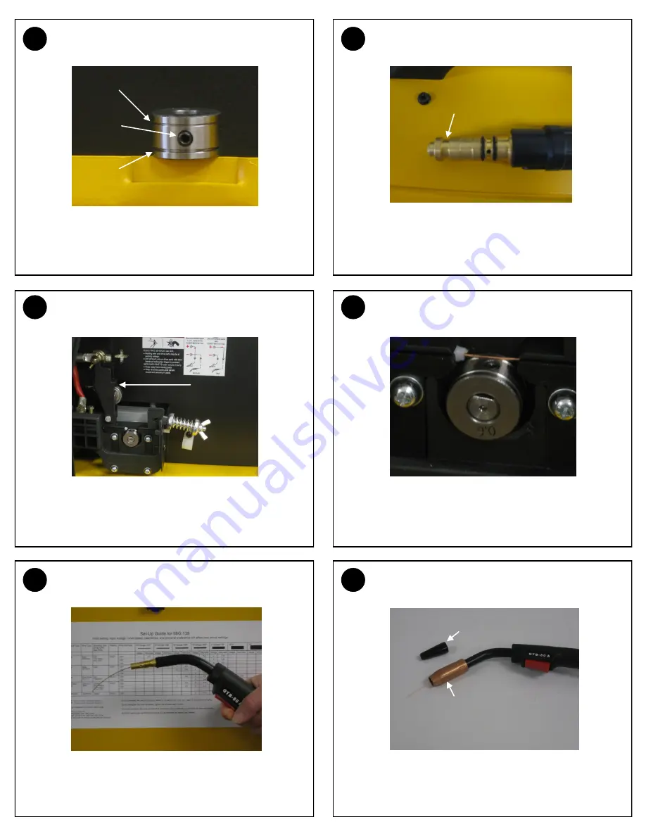
DRIVE ROLL GROOVE SELECTION
4
MIG GUN - MACHINE END
7
FEED WIRE - OPEN TENSION ARM
8
FEED WIRE - THREAD WIRE
11
FEED WIRE - PULL TRIGGER TO FEED WIRE
12
FEED WIRE - REINSTALL TIP AND NOZZLE
The smaller groove on the drive roll is to be used with .023 wire.
The larger groove can be used for .030 and .035 wire. Use the
supplied “L” shaped hex wrench to loosen set screw and to align
the proper groove to the wire path. Retighten set screw.
This MIG gun is a one piece connection. Notice the retaining
groove on the machine end. The hex-headed retaining screw in
the step (6) will set down into this groove.
Open the drive roll tension arm on the wire feeder.
Feed the loose end of the wire through the Inlet Guide Tube, past
the drive roll and into the back of the MIG Gun. Keep tension on
the wire to prevent unspooling on the spool. Make certain wire is
centered on groove and adjust drive roll (Step 3) if needed.
Stretch out the MIG gun. Turn on input power and pull the trigger
to feed the wire through the gun. Stop when the wire pushes
through the end of the gun.
Slide the correct size contact tip for the wire size you are using
over the end of the wire and tighten clockwise to secure. Choose
the correct nozzle, thread on nozzle and clip any excess wire.
.023
.030
.035
Set
Screw
Retaining
Groove
Flux-Cored Nozzle
Hard Wire
Nozzle
Drive Roll
Tension
Arm


