background image

NorthEast Monitoring, Inc.                                NEMM048-Rev-G

Page 8 of 21


DR400 User Manual 

 Recording ECG: Step 4: Hook up Patient

Step 4: Hook up Patient

1.

PCPatch Utility. 

If you want to observe lead 

quality at hook-up, start the PCPatch utility if 
not already running. Once the PCPatch utility 
finds the Bluetooth USB and is “waiting for 
DR400”, the utility is ready for you to start the 
DR400 recorder.

2.

Remove the DR400 from the docking station. 

If the DR400 was started via the PCPatch, jump 
to Step 3. 

3.

To otherwise start the DR400, press and hold 
the DR400 button down until the green light 
starts flashing.

 If the light immediately turns 

orange, this means one of two things: 1) the pre-
vious patient’s data has not been erased or 2) it 
has been erased and there is no new Patient ID. 
You will need to plug the recorder back into the 
USB and use the PCPatch utility to delete the 
file and/or enter a new Patient ID. 

4.

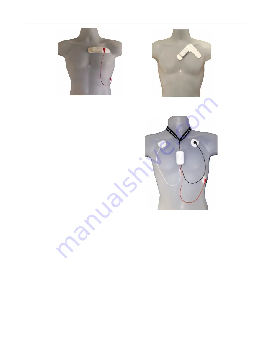
Attach electrodes to DR400.

 Attach the patch 

or adapter to the DR400. If you are using the 
optional lead wire with the 1-lead patch, attach 
it now. Press down firmly so that all snaps are 
locked in place. The 3-lead adapter lanyard 
should be placed around the patient’s neck.

5.

Attach Patch to Patient. Remove paper backing 
from patch and press firmly on to patient to 
attach. If using optional lead wire with patch, 
attach an electrode to the extension lead wire 
and attach to the patient in the proper location.

For 3-lead adapter.

 Attach electrodes to each 

lead and adhere electrodes as pictured in exam-
ple.

        1-lead patch with 

optional lead wire (3CH) 

       3-lead patch 


         3-lead adapter with lanyard placement. 
                         Electrodes required.

Summary of Contents for DR400

Page 1: ...Part number NEMM048 Rev G Revision August 25 2021 Copyright 2021 All rights reserved DR400 User Manual patch style Holter recorder with event capabilities DR400 v5 25 PCPatch v1 10 ...

Page 2: ...6 Chapter 2 Recording ECG 7 Step 1 Fully charge the DR400 7 Step 2 Start the PCPatch utility 7 Step 3 Prepare patient 7 Step 4 Hook up Patient 8 Step 5 Start Recording 9 Step 6 Copy Holter file 9 Chapter 3 PCPatch Wireless 10 DR400 Settings 11 To View Live Patient ECG 12 Wireless Event Recording 13 ETel Mobile Cardiac Telemetry MCT monitoring 14 Chapter 4 Appendices 15 Appendix A Maintenance and C...

Page 3: ...view and report on the recording The DR400 Recorder is not intended to replace real time telemetry monitoring for patients suspected of having life threatening arrhythmias The DR400 Recorder is not for In Vitro diagnostic use Specifications Physical Specifications The DR400 recorder meets the following physical specifications Size 6 8 cm length x 3 9 cm width x 1 3 cm depth Weight 33 grams 1 2 oz ...

Page 4: ... or when activated by the patient for diagnostic evaluation of transient symp toms Indications for Use 1 Detection of Arrhythmias The DR400 recorder is indicated for use in continuous monitoring of cardiac rhythm when intermit tent arrhythmia are suspected due to patient symptoms such as palpitations transient isch emic attacks TIAs syncope fainting or other such symptoms as determined by the phys...

Page 5: ...connects to a PC or power adapter Before or after a procedure firmly attach the DR400 to the docking station via two electrode snaps When attached via the snaps a connection is made when the 4 small pads on the recorder coming in contact with the 4 spring pins on the base of the docking station Once the DR400 is attached to the docking station the recorder will recharge automatically Addition ally...

Page 6: ...hEast Monitor ing will refuse delivery The usable life of the device and accessories are at least long as the war ranty period Operating the Recorder If you require training such as assistance in setting up using or maintaining your recorder contact NorthEast Monitoring or your dealer Should the recorder fail to work properly during its useful life or changes its performance stop using immediately...

Page 7: ...nt to plug it in again to ensure it is fully charged before your next study but that should only take a few minutes Step 2 Start the PCPatch utility See chapter 3 The PCPatch Utility for more information on using the PC Patch Place the fully charged DR400 into the docking station and attach the docking station to the PC using the USB cable Start the PCPatch utility and 1 ERASE any data on the DR40...

Page 8: ... or 2 it has been erased and there is no new Patient ID You will need to plug the recorder back into the USB and use the PCPatch utility to delete the file and or enter a new Patient ID 4 Attach electrodes to DR400 Attach the patch or adapter to the DR400 If you are using the optional lead wire with the 1 lead patch attach it now Press down firmly so that all snaps are locked in place The 3 lead a...

Page 9: ...h attached but we do not rec ommend that the patient go swimming or bathing while wearing either 3 Instruct the patient on how to use the PRESS but ton to indicate symptomatic events or activities of interest during the Holter test Advise them to push the PRESS button briefly 4 Provide the patient with instructions on how to use and change the patch or electrodes Wireless Event For Event recording...

Page 10: ...Plug the DR400 into the USB on the same PC where the PCPatch utility is running When a DR400 is found you can do the fol lowing Preview When a patient file is on the DR400 you can view the Recorder S N the Patient ID and the date and start time of the recording Copy Flash dat Although this button can be used to copy the flash dat file into the next open directory in HE LX soft ware we recommend th...

Page 11: ...art rate on or below this number is detected a brady event will be recorded The range is 20 100 BPM Tachy Limit If a heart rate on or above this number is detected a tachy event will be recorded The range is 50 300 BPM Pause Limit If no heart beat is detected for at least the pause length in seconds a pause event will be recorded The range is 1 0 to 10 0 seconds Separation Limits the number of eve...

Page 12: ...5 numbers should match the Serial Number of your Bluetooth USB The button is only enabled when a Bluetooth USB was found when the PCPatch utility started Using PCPatch to View ECG With the DR400 ready to record and attached to the patient start the PCPatch application Once the utility shows Waiting for DR400 hold the PRESS button down to start the recording Once the green light turns from solid to...

Page 13: ...g in Event mode the patient should charge the DR400 every 14 days at a minimum Remind the patient that the recorder will flash orange while charging and then flash green when fully charged As with Holter the patient can record an event by pressing the PRESS button quickly The recorder will flash green when recording an event Flashing will also occur when the recorder is saving an auto matically ge...

Page 14: ...ility The ETel utility is used to send MCT messages to the DR400 during the procedure The screen below shows a request that would be used to obtain ECG data ECG data requests must be within the last 24 hours Up to 10 minutes at a time can be requested Multiple requests can be sent during a single proce dure however only one request at a time can be queued for a single DR400 Additionally Auto event...

Page 15: ...or patients with a uni polar electrode configuration the signal at the surface may range from under 50 to over 200 millivolts When a bipolar lead configuration is used the signal is typically much lower and is in the range of 3 to 50 millivolts Especially with the bipolar leads the signal size is dependent on the positions of the pacemaker lead and the surface electrodes The amplitude of the signa...

Page 16: ... 3 lead adapter NEMH226 DR400 docking station NEMP00511 USB Power Port Adapter LV Sun with 3 power cord NEMP00513 Sena Parani Mfg PN SD1000U Bluetooth USB Adapter for Serial Port Appendix D Extraction of ECG data on 3 channel It is possible to retrieve the raw ECG files from the Holter files For all 3 channel data the process results in three files one for each channel Each file is then in the for...

Page 17: ...o allow the user to save patient files to HE LX Analysis 1 Ensure that the local PC has read write access to the HE LX Analysis patient directory on the server 2 On the local PC create a directory labeled c nm bin Copy the h4w ini file from a PC that has HE LX Analysis installed and paste it into the local directory The h4w ini file most likely can be found in the c nm bin directory Using Windows ...

Page 18: ...ion electromagnetic emissions The Northeast Monitoring DR400 Recorder is intended for use in the electromagnetic environment specified below The customer or user of the Northeast Monitoring DR400 Digital Recorder should ensure that it is used in such an environment Emissions Test Compliance Electromagnetic environment guidance RF emissions CISPR 11 Group 1 Northeast Monitoring DR400 Digital Record...

Page 19: ...st IEC 61000 4 4 2 kV for power supply lines 1 kV for input output lines Not applicable No cables exceed 3 meters Mains power quality should be that of a typical commercial or hospital environment Surge IEC 61000 4 5 1 kV line s to line s 2 kV line s to earth Not applicable Northeast Monitoring DR400 Recorder is battery powered N A Voltage dips short interruptions and voltage variations on power s...

Page 20: ...rer and d is the recommended separation distance in metres m Field strengths from fixed RF transmitters as determined by an electromagnetic site survey a should be less than the compliance level in each frequency range b Interference may occur in the vicinity of equipment marked with the following symbol NOTE 1 At 80 MHz and 800 MHz the higher frequency range applies NOTE 2 These guidelines may no...

Page 21: ...put power of the communications equipment Rated maximum output power of transmitter W Separation distance according to frequency of transmitter m 150 KHz to 80 MHz d 1 2 P 80 MHz to 800 MHz d 1 2 P 800 MHz to 2 5 GHz d 2 3 P 0 01 0 12 0 12 0 23 0 1 0 38 0 38 0 73 1 1 2 1 2 2 3 10 3 8 3 8 7 3 100 12 12 23 For transmitters rated at a maximum output power not listed above the recommended separation d...

Reviews: