background image

Norsonic  Nor1212

User Guide

9


If the mast is high and you need to make regular calibrations or other 
service operations, we recommend the use a tiltable or a telescopic mast. 
Norsonic can supply different masts on demand. 

Fasten the microphone cable along the mast properly. A cable flapping 
onto the mast in windy conditions may create excessive noise and ruin the 
measurement accuracy. 

3.4 

Grounding and lightening protection 

If the outdoor microphone assembly is the highest object in the vicinity 
when mounted, it may be exposed to lightening strikes. We recommend 
that the mast, if conductive, is properly grounded. 

A lightening rod in proper contact with a conductive mast will form a 
suitable protection against the effects of a lightening strike and a 
recommended configuration is given below.. The rod should be placed at 
least 25 cm to the side of the microphone assembly and have a diameter 
not more than 10 mm in order not to interfere with the direction properties 
of the microphone. Its height should be at least 10 cm above the tip of the 
microphone assembly (the microphone is located 14 cm below the 
insulated tip). If the mast is not conductive, the lightening rod should be 
connected to a proper lightening conductor. 

Safety considerations may require that the screen of the microphone cable 
to be properly grounded. We recommend making the combined 
grounding for the cable and instrument at one point only in order to 
reduce the risk of pick-up of hum and electro-magnetic noise. Verify the 
noise floor of the complete system after installation is completed to 
ensure it is below the lower end of the required measurement range. If a 
quiet location is not available, the noise floor may be measured by 
substituting the microphone with a dummy microphone like Nor1448. As 
an alternative the Nor1447 adaptor terminated with a short-circuit or a 50 
ohm BNC termination is also a suitable device for making this test. 

Figure 3.3 Lightening 
protection 


Summary of Contents for Nor1212

Page 1: ...Instruction Manual Outdoor Microphone Kit Nor1212 Im1212_1Ed1R1En May 2004 ...

Page 2: ......

Page 3: ...Instruction Manual Outdoor Microphone Kit Nor1212 Im1212_1Ed1R1En May 2004 ...

Page 4: ...ibed herein Furthermore Norsonic AS assumes no responsibility for any infringement of the intellectual property rights of third parties wherever applicable which could result from such use Norsonic AS reserves the right to amend any of the information given in this manual in order to take account of new developments If you wish to communicate with us please feel welcome Our address is Norsonic AS ...

Page 5: ...mbling the outdoor microphone unit 7 3 3 Mounting on a mast 8 3 4 Grounding and lightening protection 9 4 Microphone Calibration 11 5 Maintenance 13 6 Specifications 15 6 1 Mounting direction 15 6 2 Acoustic performance 15 6 2 1 Frequency response 15 6 2 2 Directional response 16 6 3 General 20 6 4 Accessories and spare parts 20 ...

Page 6: ......

Page 7: ...one along the axis of symmetry When mounted for outdoor measurements the microphone is normally mounted with the diaphragm pointing upwards The microphone response will therefore be at its best for sound from above Even for aircraft noise monitoring the sound will seldom approach the microphone just from this direction The outdoor kit has therefore been designed to change the directional character...

Page 8: ...4 Introduction For improved protection in excessive humid applications the outdoor kit may be combined with a microphone desiccator or the preamplifier may be heated ...

Page 9: ...ect the microphone system to the measuring instrument with a coaxial cable we recommend to use the pre polarised microphone Nor1227 in combination with a suitable ICP type of preamplifier We recommend Nor1207 with desiccator TA202 You need the desiccator due to the size of Nor1207 The outdoor kit Nor1212 protects the normal measurement microphone Nor1225 from rain dust and insects which sometimes ...

Page 10: ... the handbook for Nor1201 for further details Alternatively a desiccator type TA202 may be placed between the microphone and the preamplifier The desiccator absorbs water and hence provides dry air to the microphones back vent The desiccator needs to be regenerated from time to time see section 5 for information about this maintenance operation Placing the microphone inside a long rod results in t...

Page 11: ...is very important in order to retain the normal polarisation voltage for the microphone If you need weather protected connectors we recommend cable type Nor1485 Depending on the application you will need a mast or tripod for mounting the microphone system and possibly also devices for proper grounding and lightening protection See below 3 2 Assembling the outdoor microphone unit See figures 2 1 2 ...

Page 12: ...and force only and do not over tighten The purpose of the base screw is threefold Important Follow the mounting instructions carefully otherwise the microphone may be harmed It is a base for mounting the microphone system on a mast or tripod It closes the main body but has a water drain to let any condensate escape Figure 3 2 The desiccator TA202 is placed between the microphone and the preamplifi...

Page 13: ...and have a diameter not more than 10 mm in order not to interfere with the direction properties of the microphone Its height should be at least 10 cm above the tip of the microphone assembly the microphone is located 14 cm below the insulated tip If the mast is not conductive the lightening rod should be connected to a proper lightening conductor Safety considerations may require that the screen o...

Page 14: ......

Page 15: ...26 and Nor1227 Screw off the upper part of the protector kit to gain access to the microphone Mount the calibrator and switch it on See figure 4 1 If the calibrator frequency is 250 Hz adjust the reading to be the level stated for the calibrator e g 124 0 dB for Nor1253 with 124 dB specified level If the calibrator frequency is 1000 Hz adjust the reading to be 0 2 dB below the stated calibrator le...

Page 16: ...12 ...

Page 17: ... in coastal installations it may be necessary to replace the windscreen earlier Remove the upper protection part and verify that the mesh covering the acoustic ports is clean and free from dust You may inspect the mesh by holding it in front of a light source rotate the upper protection part and look through the holes Use a soft brush to wipe off any dust or detritus If heavily polluted peel off t...

Page 18: ......

Page 19: ...tical axis 6 2 Acoustic performance 6 2 1 Frequency response The modification of the free field response and the random incidence response of a Nor1225 microphone when placed in the outdoor kit Nor1212 is shown on the diagram below together with the requirements for a Class 1 sound level meter according to IEC61672 1 Both the free field and the random incidence response shown are referred to the f...

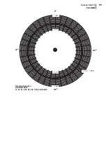
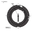
Page 20: ...dom incidence response Tolerance limits with uncertainty IEC 61672 1 Class 1 6 2 2 Directional response The directional response satisfies the requirements for a Class 1 sound level meter according to IEC61672 1 The figures on the next pages show the directional response in detail in a plane through the horizontal and vertical axis of symmetry ...

Page 21: ...se Horizontal plane 1k 2k 4k 6 3k 8k 10k 12 5k and 16kHz 1 k 2k 16kHz 90o 180o 270o 5 dB 5 dB 7 dB Norsonic Nor1212 User Guide 17 Directional response Horizontal plane 1k 2k 4k 6 3k 8k 10k 12 5k and 16kHz 1 k 2k 16kHz 0o 90o 180o 270o 5 dB 5 dB 7 dB 7 dB ...

Page 22: ...k and 6 3kHz 1 kHz 2 kHz 4 kHz Reference direction 0o 6 3 kHz 6 3 kHz 90o 180o 270o 5 dB 5 dB 7 dB 18 Specifications Directional response Vertical plane 1k 2k 4k and 6 3kHz 1 kHz 2 kHz 4 kHz 6 3 kHz 6 3 kHz 0o 90o 180o 270o Reference direction 5 dB 5 dB 7 dB 7 dB ...

Page 23: ...k 12 5k and 16kHz 8 kHz 10 kHz 12 5 kHz 16 kHz 0o Reference direction 90o 180o 270o 5 dB 5 dB 7 dB Norsonic Nor1212 User Guide 19 Directional response Vertical plane 8k 10k 12 5k and 16kHz 8 kHz 10 kHz 12 5 kHz 16 kHz 0o 90o 180o 270o Reference direction 5 dB 5 dB 7 dB 7 dB ...

Page 24: ...lowing standards EN 50081 1 EN 50082 1 6 5 Accessories and spare parts Desiccator TA202 Windshield Nor4520 Dust mesh Norsonic part no 0896000 Microphone Nor1225 Microphone preamplifier Nor1201 Nor1206 or Nor1207 Sound calibrator Nor1251 or Nor1253 Microphone cable Nor1408 Standard lengths 5 10 15 20 30 and 50 metres other lengths on request Dummy microphone Nor1448 18 pF or Nor1447 with a short ci...

Page 25: ......

Page 26: ...P O Box 24 N 3421 Lierskogen Norway www norsonic com ...

Reviews: