10
important! On variable speed models when the unit is
used in an air conditioning system, connect the o terminal
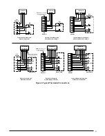
to the Y terminal. See Figure 9 (page 20).
control Board
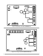
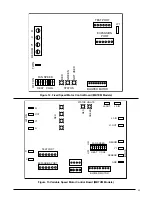
The control board in the air handler controls the timing
sequence of the elements. Depending on the thermostat
connection, there are multiple timing sequence variations
that can be chosen. The board also is equipped with a 3
second blower on delay and a 15 second blower off delay.
See Figures 10 - 13 (pages 22 & 23) for control board layout
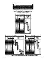
and Tables 10 & 11 (pages 27-29) for element sequences.
Twinning
MB7 air handlers are not supplied with a built in twinning
capability. To connect two air handlers to a common single
stage AC condensing unit or heat pump, a twinning kit
is available for field installation. iMPortant: Variable
speed air handlers cannot be twinned. Please follow
the instructions supplied with the kit.
Heater Kits
Field-installed electric heater kits are available. Instructions
for installing the electric heaters are included with the
heaters. Additional heater kit information can be found in
the units Technical Specifications.
Air handlers set up with 15 kw or more of electric heat will
normally be configured for multiple-circuit power supply.
They may, however, be connected to a single-circuit power
supply with the addition of a single circuit accessory
kit. Select the wire size and over-current protection
in accordance with the minimum circuit ampacity and
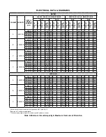
maximum over-current protection shown in Table 9. See
also the units Technical Specifications.
When electric heat packages with circuit breakers are
field-installed, the circuit breaker may be used as a
disconnecting means in most applications. Reference the
NEC and local codes for disconnect requirements.
If a heater kit is installed:
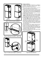
The MB7 air handler is shipped from the factory without
an electric heater kit installed. If Electric heat is desired,
the H6HK heater kit may be purchased separately and
field installed. Determine the correct size heater kit for your
unit by referring to the list below or the units rating label.
A Size Cabinet ............................................... 15Kw max
B Size Cabinet ............................................... 20Kw max
C Size Cabinet ............................................... 20Kw max
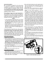
1. Connect the 2 wire plug of the air handler to the mating
2 wire plug of the heater kit.
2. Connect the line voltage leads to the circuit breaker or
terminal block provided.
3. Connect the heater kit plug with the mating receptacle
on the air handler control board.
If a heater kit is not installed:
1. Remove the 2 wire plug of the air handler by cutting the
wires and discarding the plug.
2. Strip the ends of the 2 air handler wires and connect
to the line-voltage leads with the 2 wire nuts provided.
electronic air cleaner (eac)
The unit has an output to power an electronic air cleaner
when the blower is running. This output is rated to 1.0
amp at 208/240V.
Humidifier
The unit has an output to power a humidifier when the
blower is running. This output is rated to 1.0 amp at
208/240V.
optional Humidistat
(MB7EM or MB7VM Models Only)
The optional humidistat may be installed in the return air
duct to provide excellent humidity control when needed
and maximum system capacity and energy efficiency when
humidity levels are normal. The humidistat senses when
humidity in the return air stream is above a preset level
(field adjustable) and sends a signal to the motor to reduce
the airflow so that more moisture may be removed until the
humidity level drops. The air handler is pre-programmed
for humidistat operation.
Install the humidistat in the return air duct as directed in
the installation instructions included with the kit. Wire the
humidistat through the low-voltage wire entrance in the
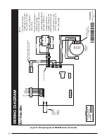
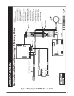
air handler to the control board terminal marked deHuM.
Wire the humidistat to open on rise in humidity.
Grounding
WarninG:
the unit cabinet must have an uninterrupted or
unbroken electrical ground to minimize personal
injury if an electrical fault should occur. do not
use gas piping as an electrical ground!
This unit must be electrically grounded in accordance
with local codes or, in the absence of local codes, with
the National Electrical Code (ANSI/NFPA 70) or the CSA
C22.1 Electrical Code. Use the grounding lug provided in
the control box for grounding the unit.


