4-18
Operation
4.8 Camera Operation
The S2-900 Series features a Dalsa-Coreco Genie M640 digital 640 x 480 pixel camera. It communicates
bi-directionally to the laptop computer via Gigabit Ethernet. The camera is configured to run at 60 full
frames per second. A frame can be transferred in 16.67 milliseconds. The S2-900P is configured with
Monocle™ Vision. Refer to the
Monocle Vision Package Owner’s Manual
for detailed instructions.
4.8.1 Camera States
After the Dalsa-Genie software package has been installed, the GigE Server icon will be visible in the
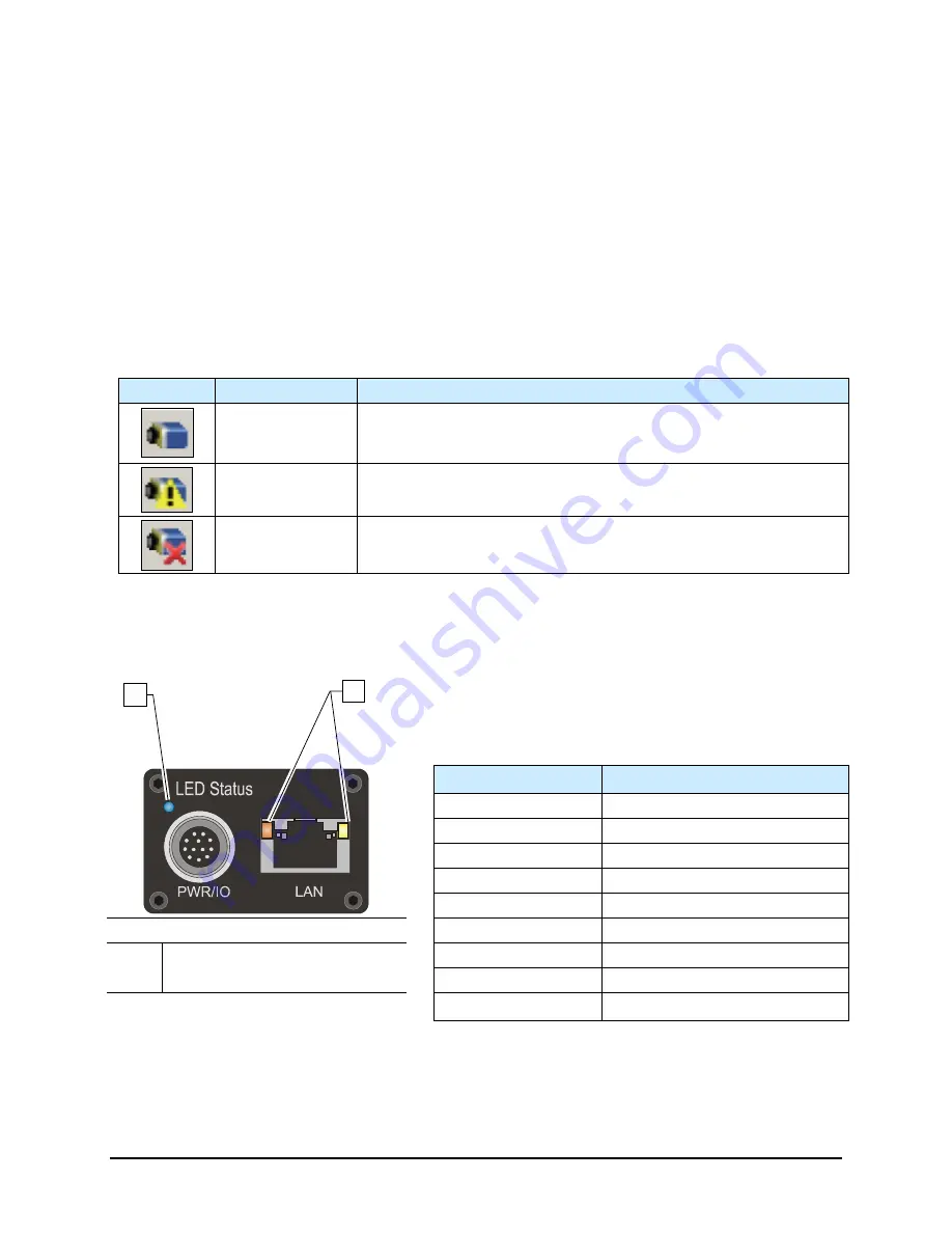
desktop taskbar tray area. The icons and descriptions are shown in Table 4-5.
NOTE
The Dalsa-Genie software is installed at the factory prior to shipping.
Table 4-5 Genie Camera States
Icon
State
Description
Device Available
The GigE server tray icon when the Genie device is found. It will
take a few seconds for the GigE Server to refresh its state after the
Genie has obtained an IP address.
Device IP Error
The GigE server tray icon shows a warning when a device is
connected but there is some type of IP error.
Device Not
Available
A red X will remain over the GigE server tray icon when the Genie
device is not found. This indicates a major network issue.
The Genie has one multicolor LED to provide a simple visible indication of camera state. Additionally the
RJ45 has two LEDs for network status conditions (Figure 4-14). LED Status indicators are described in
Table 4-6.
Table 4-6 Camera Status Indicators
LED Status
Description
LED is OFF
No power to camera
Steady Red
Camera Not Initialized
Slow Flashing Red
Camera Initialization Problem
Fast Flashing Red
Camera Overheating
Steady Blue
IP Address Assigned
Item
Description
Slow Flashing Blue
Waiting for an IP Address
1
Camera Status LED
Fast Flashing Blue
Ethernet Cable Disconnected
2
Network Status LEDs
Steady Green
Application Linked to the Camera
Figure 4-14 Camera LEDs (Rear View)
Slow Flashing Green Trigger Acquisition in Progress
1
2
Summary of Contents for Spectrum II S2-900 C Series
Page 2: ......
Page 36: ...1 22 Introduction 1 11 8 Rear View Open Figure 1 9A S2 900 Rear View Open 1 2 3 4...
Page 40: ......
Page 124: ......
Page 157: ...Calibration and Adjustment 5 33 Figure 5 38 Dispense Lift Table Controls...
Page 159: ...Calibration and Adjustment 5 35 Figure 5 40 Beacon Configuration Window...
Page 186: ......
Page 197: ...Troubleshooting 7 11 Figure 7 1 Scale Setup Menu Figure 7 2 Scale Error Message...
Page 200: ......
Page 215: ...Parts Replacement 8 15 Figure 8 11 Replacing a Panel Mounted Fuse...
Page 218: ......
Page 223: ...Specifications 9 5 Top View mm Back View mm Figure 9 2 S2 900 System Dimensions 2 of 2...
Page 225: ...Specifications 9 7 Top View mm Back View mm Figure 9 4 S2 9XXC System Dimensions 2 of 2...
Page 228: ...A 2 Appendix A Material Safety Information A 2 1 Multemps PS NO 2...
Page 229: ...Appendix A Material Safety Information A 3...
Page 230: ...A 4 Appendix A Material Safety Information...
Page 231: ...Appendix A Material Safety Information A 5...
Page 232: ...A 6 Appendix A Material Safety Information...
Page 233: ...Appendix A Material Safety Information A 7...
Page 235: ...Appendix A Material Safety Information A 9...
Page 236: ...A 10 Appendix A Material Safety Information...
Page 237: ...Appendix A Material Safety Information A 11...
Page 238: ...A 12 Appendix A Material Safety Information...
Page 239: ...Appendix A Material Safety Information A 13...
Page 240: ...A 14 Appendix A Material Safety Information...
Page 246: ......
Page 252: ......
Page 258: ......


