


7
2.3
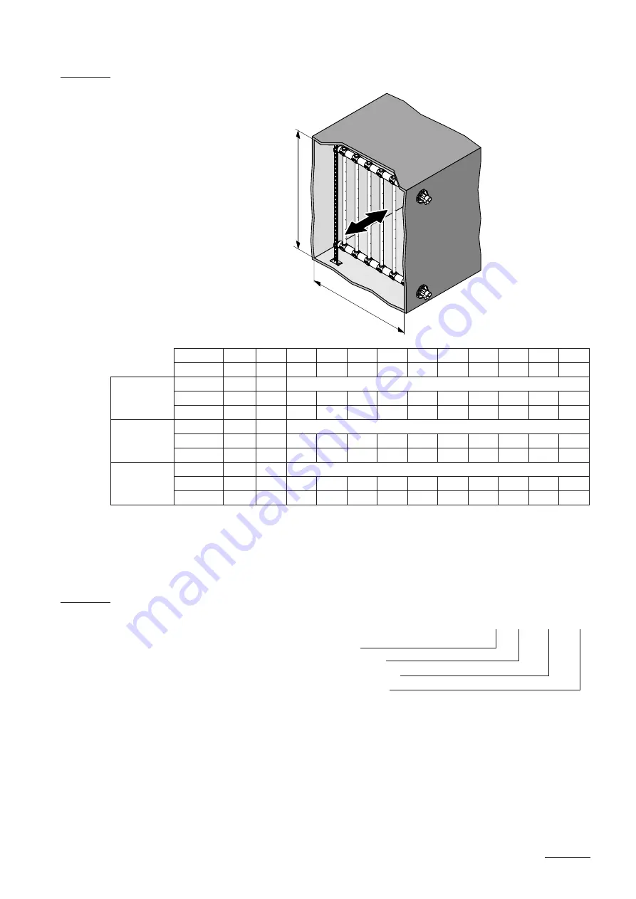
Power selection diagram MultiPipe Systems 1...4
L
mm
350
500
650
800
1000 1200 1500 1800 2000 2300 2500
B min.
mm
450
600
750
900
1100 1300 1600 1900 2200 2500 2700
System 1 **
m
D
max.
kg/h
23
32
D2
mm
350
500
650
800
1000 1200 1500
H min.
mm
450
600
800
950
1150 1350 1650
System 2 **
m
D
max.
kg/h
45
65
D2
mm
350
500
650
800
1000 1200 1500 1800 2000
H min.
mm
450
600
800
950
1150 1350 1650 1950 2200
System 4 ***
m
D
max.
kg/h
90
130
D2
mm
300
375
475
575
725
875
1050 1200 1350 1500
H min.
mm
800
950
1150 1350 1650 1950 2300 2600 2900 3200
**
Systems 1 and 2 for single units only
***
System 4 for double units only
2.4
Type key
X / XXX / XXX / XXX
No. MultiPipe system
Collector length “L” in [mm]
Collector distance “D2” in [mm]
Steam capacity “m
D
” in [kg/h]
H
B