background image

3

1. Read all instructions in this manual and all

warnings on the resistance system before
using the resistance system. Use the resist-
ance system only as described in this
manual. 

2. It is the responsibility of the owner to ensure

that all users of the resistance system are
adequately informed of all precautions.

3. The resistance system is intended for home

use only. Do not use the resistance system in
any commercial, rental, or institutional set-
ting.

4. Keep the resistance system indoors, away

from moisture and dust. Place the resistance
system on a level surface, with a mat beneath
it to protect the floor or carpet. Make sure
that there is enough clearance around the
resistance system to mount, dismount, and
use it.

5. Inspect and properly tighten all parts regular-

ly. Replace any worn parts immediately. 

6.   Keep children under age 12 and pets away

from the resistance system at all times.

7.  Keep hands and feet away from moving parts.

8. Always wear athletic shoes for foot protec-

tion while exercising.

9. The resistance system is designed to support

a maximum user weight of 300 pounds (136
kg). 

10. Make sure that the cables remain on the pul-

leys at all times. If the cables bind while you
are exercising, stop immediately and make
sure that the cables are on the pulleys.
Replace all cables at least every two years.

11. Always stand on the base plate when per-

forming an exercise that could cause the
resistance system to tip.

12. Use the resistance system only with the

included resistance. Do not use the resist-
ance system with any other type of weight to
add resistance.

13. Always make sure that the pins and knobs

are fully engaged before using the resist-
ance system.

14. If you feel pain or dizziness at any time while

exercising, stop immediately and begin cool-
ing down. 

WARNING:

Before beginning this or any exercise program, consult your physician. This

is especially important for persons over the age of 35 or persons with pre-existing health problems.
Read all instructions before using. ICON assumes no responsibility for personal injury or property
damage sustained by or through the use of this product. 

WARNING: 

To reduce the risk of serious injury, read the following important precautions

before using the resistance system.

IMPORTANT PRECAUTIONS

Summary of Contents for NTSY9896.0

Page 1: ...NTSY9896 0 Serial No Write the serial number in the space above for future reference QUESTIONS As a manufacturer we are com mitted to providing complete customer satisfaction If you have questions or...

Page 2: ...IST 18 EXPLODED DRAWING 19 ORDERING REPLACEMENT PARTS Back Cover LIMITED WARRANTY Back Cover NordicTrack is a registered trademark of ICON IP Inc TABLE OF CONTENTS The decals shown here have been plac...

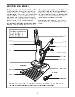
Page 3: ...is designed to support a maximum user weight of 300 pounds 136 kg 10 Make sure that the cables remain on the pul leys at all times If the cables bind while you are exercising stop immediately and mak...

Page 4: ...ur goal is to tone your body build dramatic muscle size and strength or improve your cardiovascular system the resistance system will help you to achieve the specific results you want For your benefit...

Page 5: ...crew 59 M6 Washer 82 PART IDENTIFICATION CHART See the drawings below to identify small parts used in assembly The number in parentheses by each drawing is the key number of the part from the PART LIS...

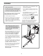
Page 6: ...ratchet wrenches Make Assembly Easier Everything in this manual is designed to ensure that the resistance system can be assembled successfully by almost anyone By setting aside plenty of time assembly...

Page 7: ...M6 x 80mm Button Screws 68 and three M6 Washers 82 Press the Upright Cap 33 into the top of the Base 1 4 Make sure that all parts are properly tight ened The use of the remaining parts will be explain...

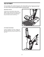
Page 8: ...stance system ADJUSTING THE SEAT The Seat 24 can be attached at either of two heights To raise or lower the Seat 24 lift it off the pins on the Base 1 and set it on a different set of pins For exercis...

Page 9: ...en the Adjustment Handle is in the desired position release it Push the Adjustment Handle forward or backward slightly to make sure that it is fully engaged 9 7 34 11 6 Screws Link 38 TIGHTENING THE C...

Page 10: ...nd tone workouts for the upper and lower body During each build and tone workout the voice of a personal trainer will prompt you to perform a series of strength exercis es The console also features th...

Page 11: ...ice of the con sole and the display will count the repetitions as you perform them At the end of a set rest for the amount of time shown in the display Then resume performing repetitions and sets as i...

Page 12: ...begin explaining the first exer cise The name of the exercise and an animation of the exercise will then appear on the screen Touch the READY button at any time during the explana tion to begin the e...

Page 13: ...When you select a target exercise the voice of a personal trainer will begin explaining the exercise The name of the exercise and an animation of the exercise will then appear on the screen Touch the...

Page 14: ...n explaining the first exercise The name of the exercise and an ani mation of the exercise will then appear on the screen Touch the READY button at any time dur ing the explanation to begin the exerci...

Page 15: ...ace down and are facing the slot When the iFIT Card is properly inserted the indicator next to the slot will light and an iFIT menu will appear on the screen Next select the desired workout on the iFI...

Page 16: ...tings and exit the display settings screen Note The LCD backlight setting will not be saved in memory for the next time you turn on the console HOW TO ADJUST THE AUDIO SETTINGS When you touch the AUDI...

Page 17: ...to each stretch gradually and go only as far as you can without strain Move slowly as you stretch and do not bounce Stretching at the end of each workout is an effective way to increase flexibility St...

Page 18: ...Console Wire Harness 42 1 3 pin Wire Harness 43 4 Arm Bushing 44 4 Pulley Bushing 45 4 Barrel Nut 46 2 Pivot Pulley Bearing 47 1 Handle Spring 48 2 Arm Cap 49 2 Weight Clip 50 1 Left Retainer Clip 51...

Page 19: ...8 43 43 44 44 45 50 46 48 51 52 73 68 59 59 74 82 68 19 85 85 65 65 85 58 85 80 80 56 65 85 79 88 75 85 81 81 58 9 9 10 10 70 61 61 70 60 85 64 8 12 13 14 15 16 17 31 35 49 47 39 55 66 83 77 76 69 71...

Page 20: ...product for repair USER S MANUAL It is VERY IMPORTANT THAT YOU READ THE MANUAL before operating the Product Remember to do the periodic maintenance requirements specified in the Manual to assure prop...

Reviews: