NordicTrack NTEX05119.6 User Manual Download Page 18

18

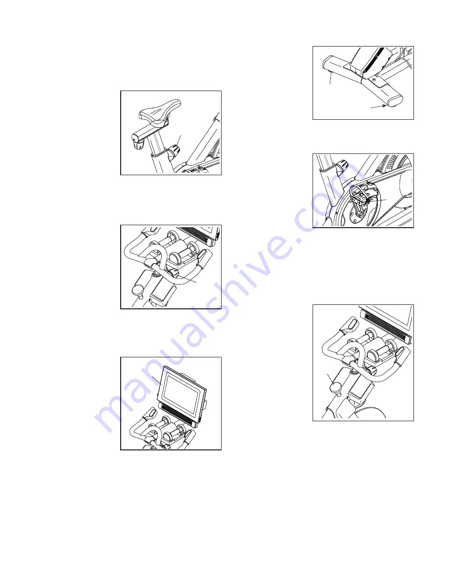
How to Adjust the Saddle Post

For effective training, the saddle should be at the 

proper height. As you pedal, there should be a slight 

bend in your knees when the pedals are in the lowest 

position. 

To adjust the saddle 

post, loosen the 

post knob (C), 

move the saddle 

post upward or 

downward, and 

then firmly tighten 

the post knob. 

IMPORTANT: Do 

not raise the sad-

dle post beyond 

the “MAX” mark on the saddle post. 

How to Adjust the Handlebar Post

To adjust the han-

dlebar post, loosen 

the post knob (D), 

move the handle-

bar post upward 

or downward, and 

then firmly tighten 

the post knob. 

IMPORTANT: 

Do not raise the 

handlebar post 

beyond the “MAX” mark on the handlebar post.

How to Adjust the Position of the Console

The console (E) can 

be adjusted upward, 

downward, or to 

the side. To adjust 

the position of the 

console, simply 

hold the sides of the 

console and press 

it to the desired 

position. You can 

pivot the console all 

the way to the side 

so that you can view it while standing next to the studio 

cycle to perform hand weight exercises or other floor 

exercises.

HOW TO LEVEL THE STUDIO CYCLE

If the studio cycle 

rocks slightly on 

your floor during 

use, turn one or 

both of the leveling 

feet (F) beneath the 

rear stabilizer until 

the rocking motion 

is eliminated.

HOW TO USE THE PEDALS

To use the pedals, 

insert your shoes 

into the toe cages 

and pull the ends 

of the toe straps. 

To adjust the toe 

straps, press and 

hold the tabs (G) on 

the buckles, adjust 

the toe straps to the 

desired position, and then release the tabs.

Note: You can remove the pedals and attach your 

own pedals to the studio cycle if desired. 

HOW TO USE THE BRAKE KNOB

To change the 

resistance of the 

pedals, press the 

buttons on the right 

handlebar (see step 

3 on page 22). To 

stop the flywheel, 

push the brake 

knob (H). The 

flywheel will quickly 

come to a complete 

stop.

C

E

F

F

G

H

D

Summary of Contents for NTEX05119.6

Page 1: ...this equipment Keep this manual for future reference nordictrack com Serial Number Decal To register your product and activate your warranty today go to my nordictrack com For service at any time go t...

Page 2: ...NORDICTRACK and IFIT are registered trademarks of ICON Health Fitness Inc The Bluetooth word mark and logos are registered trademarks of Bluetooth SIG Inc and are used under license Google Maps is a t...

Page 3: ...e indoors away from moisture and dust Do not put the studio cycle in a garage or covered patio or near water 7 Place the studio cycle on a level surface with at least 2 ft 0 6 m of clearance around th...

Page 4: ...ur back 18 The studio cycle does not have a freewheel the pedals will continue to move until the flywheel stops Reduce your pedaling speed in a controlled way 19 To stop the flywheel quickly press the...

Page 5: ...5 STANDARD SERVICE PLANS...

Page 6: ...dio cycle If you have questions after reading this manual please see the front cover of this manual To help us assist you note the product model number and serial number before contacting us The model...

Page 7: ...e part from the PART LIST near the end of this manual The number following the key number is the quantity needed for assembly Note If a part is not in the hardware kit check to see if it has been prea...

Page 8: ...uded tool s assembly requires the following tool s one Phillips screwdriver one adjustable wrench one rubber mallet Assembly may be easier if you have a set of wrenches ASSEMBLY 1 1 Go to my nordictra...

Page 9: ...nset drawing Finish attaching the Front Stabilizer 3 with two additional M10 x 20mm Screws 105 Then fully tighten all six M10 x 20mm Screws 105 See the inset drawing Press the right Leg Cover 64 downw...

Page 10: ...105 4 4 See the inset drawing Orient the Handlebar Post 7 so that the lower slot A is on the side shown Next loosen the indicated Post Knob 100 and insert the Handlebar Post 7 into the Frame 1 until t...

Page 11: ...m Bolt 94 and an M10 Locknut 135 make sure that the Locknut is in the hexagonal hole D Do not fully tighten the Bolt yet Avoid pinching the wires C 6 D C 94 8 97 135 5 Insert the Handlebar 97 into the...

Page 12: ...8 7 97 122 125 124 7 123 8 Have a second person hold the Console 10 near the Console Bracket 11 Plug the Upper Yellow Wire 123 and the Extension Red Wire 124 into the receptacles on the back of the Co...

Page 13: ...that the largest opening E is facing forward Tip Avoid pinching the wires C Attach the Hand Weight Tray 38 to the Console Support 8 with four 8 x 5 8 Screws 17 start all the Screws and then tighten th...

Page 14: ...the Saddle Clamps 52 53 Make sure that both rails are in the grooves in the Saddle Clamps and that the Saddle is straight and level Then firmly tighten the Saddle Screw 41 11 54 54 a b 53 52 52 53 F F...

Page 15: ...e Hand Weights in the Hand Weight Tray 38 after each use 13 14 After the studio cycle is assembled inspect it to make sure that it is assembled correctly and that it functions properly Make sure that...

Page 16: ...let is not available The lug E or wire extending from the adapter must be connected with a metal screw F to a permanent ground such as a properly grounded outlet box cover Some 2 pole receptacle outle...

Page 17: ...nce workouts around the world HOW TO ADJUST THE GEOMETRY OF THE STUDIO CYCLE The studio cycle can be adjusted to match the geom etry of your road bike to promote correct form and to ensure proper trai...

Page 18: ...d the sides of the console and press it to the desired position You can pivot the console all the way to the side so that you can view it while standing next to the studio cycle to perform hand weight...

Page 19: ...he pedals and the incline of the frame as it guides you through an effective exercise session When you use the manual mode of the console you can change the resistance of the pedals and the incline of...

Page 20: ...step 6 on page 21 and manually calibrate the incline system HOW TO USE THE TOUCH SCREEN The console features a tablet with a full color touch screen The following information will help you use the to...

Page 21: ...pdates First touch the menu button three horizontal lines symbol touch Settings touch Maintenance and then touch Update The console will check for firm ware updates For more information see HOW TO CHA...

Page 22: ...l determine which workout information is shown Drag upward on the screen to enter the fullscreen display mode Drag downward on the screen to view the workout information displays Touch the various wor...

Page 23: ...the buttons at the bottom of the screen to select either the main menu Home button or the workout library Browse button 3 Select a workout To select a workout from the main menu or the workout library...

Page 24: ...scription is an estimate of the number of calories that you will burn during the workout The actual number of calories that you burn will depend on various factors such as your weight In addition if y...

Page 25: ...s on the screen Touch the screen to add the start point for your workout Then touch the screen to add the end point for your workout If you want to start and end your workout at the same point touch C...

Page 26: ...hree horizontal lines symbol on the screen and then touch Log in to log in to your iFit account Follow the prompts on the screen to enter your username and password To switch users within your iFit ac...

Page 27: ...omize workout settings To customize workout settings touch In Workout and then touch the desired settings It is recommended that you enable the option to show slider controls on the screen if availabl...

Page 28: ...the wireless network menu Touch the menu button three horizontal lines symbol and then touch Wi Fi to select the wire less network menu 3 Enable Wi Fi Make sure that Wi Fi is enabled If it is not ena...

Page 29: ...nnect your device to the console 4 Erase the console device memory if necessary If you need to erase all the Bluetooth compatible devices saved in the console memory press and hold the Bluetooth Audio...

Page 30: ...nd on try to correct the interference by one or more of the following measures Reorient or relocate the receiving antenna Increase the separation between the equipment and the receiver Connect the equ...

Page 31: ...the Console stays in place If the console does not boot up properly or if the console freezes and does not respond reset the console to the fac tory default settings IMPORTANT Doing this will erase a...

Page 32: ...ve the three indicated 8 x 5 8 Screws 17 from the Right and Left Shields 30 32 Then carefully pull the tops of the Right and Left Shields 30 32 apart a few inches See the inset drawing Slightly loosen...

Page 33: ...io cycle Remove the indicated 8 x 5 8 Screw 17 and the Shield Cover 31 from each side of the studio cycle Next loosen the M10 Axle Nut 27 on each side of the studio cycle and tighten the Adjustment Nu...

Page 34: ...rm aerobic exercise which is activity that requires large amounts of oxygen for prolonged periods of time For aerobic exercise adjust the intensity of your exercise until your heart rate is near the h...

Page 35: ...lles Stretch With one leg in front of the other reach forward and place your hands against a wall Keep your back leg straight and your back foot flat on the floor Bend your front leg lean forward and...

Page 36: ...mmet 45 1 Right Saddle Post Sleeve 46 1 Left Saddle Post Sleeve 47 1 Right Handlebar Post Sleeve 48 1 Left Handlebar Post Sleeve 49 2 Wheel 50 1 Adjustment Arm 51 1 Resistance Disc 52 1 Lower Saddle C...

Page 37: ...ire 125 1 Control Wire 126 2 M8 x 12mm Screw 127 8 M8 Large Washer 128 2 M5 Nut 129 1 M5 x 8mm Screw 130 1 6 x 5 8 Screw 131 1 Adjustment Block 132 2 M4 x 10mm Blunt Screw 133 1 Shoe Pin 134 1 Plastic...

Page 38: ...78 76 76 98 99 49 29 120 17 17 105 105 138 138 108 108 86 40 44 44 74 75 58 59 66 66 58 126 143 149 147 136 133 102 148 146 145 126 61 61 127 127 127 127 66 68 62 69 69 57 55 55 65 63 63 17 17 17 17 8...

Page 39: ...4 53 67 41 13 110 110 113 113 135 139 134 114 114 109 123 17 8 17 70 72 71 73 97 55 94 38 111 111 112 124 17 132 132 125 28 47 25 39 30 17 17 17 17 31 17 14 33 16 135 135 21 57 57 57 32 96 96 15 56 19...

Page 40: ...ct is used as a store display model 2 if the product is purchased or transported outside the USA 3 if all instructions and warnings in this manual are not followed 4 if the product is abused or improp...

Reviews: