background image

25

HOW TO SET UP THE CONSOLE 

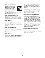
Before using the treadmill for the first time, set up the 

console. 

1.  Connect to your wireless network.


Note: In order to access the Internet, download 

iFit workouts, and use several other features of 

the console, you must be connected to a wireless 

network. See HOW TO USE THE WIRELESS 

NETWORK MODE on page 4 to connect the con-

sole to your wireless network.

2.  Check for firmware updates.

   First, see step 1 on page 31 and step 2 on page 

33 and select the maintenance mode. Then, 

see step 3 on page 33 and check for firmware 

updates.

3.  Calibrate the incline system.


See step 4 on page 34 and calibrate the incline 

system of the treadmill.

4.  Create an iFit account.


Touch the globe button near the lower left corner of 

the screen and touch the iFit button.


Note: For information about navigating in the 

browser, see page 33. The browser will open to 

the iFit.com home page. Follow the prompts on the 

website to sign up for your iFit membership. If you 

have an activation code, select the code activation 

option.

The console is now ready for you to begin working out. 

The following pages explain the various workouts and 

other features that the console offers.

To use the manual mode, 

see this page.

 To use 

an onboard workout, 

see page 27.

 To use a 

set-a-goal workout, 

see page 28. 

To use an iFit 

workout, 

see page 29.

To use the equipment settings mode, 

see page 31. 

To use the sound system, 

see page 32.

 To use the 

Internet browser, 

see page 33.

 To use the main-

tenance mode, 

see page 33.

 To use the wireless 

network mode, 

see page 34.

To operate the digital TV, 

see page 35. 

To use 

the entertainment mode, 

see page 36. 

To use the 

remote control, 

see page 36. 

To adjust the TV set-

tings, 

see page 37. 

To troubleshoot the digital TV,


see page 42.


IMPORTANT: If there are sheets of plastic on the 

console, remove the plastic. To prevent damage 

to the walking platform, wear clean athletic shoes 

while using the treadmill. The first time you use 

the treadmill, observe the alignment of the walking 

belt, and center the walking belt if necessary (see 

page 42).

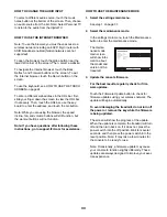
HOW TO USE THE MANUAL MODE

1.  Insert the key into the console.


See HOW TO TURN ON THE POWER on page 

24. 

Note: It may take a minute for the console 

to be ready for use.

2.  Select the main menu.

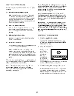
   When you turn 

on the power, 

the main menu 

will appear 

after the 

console boots 

up. Touch the 

home button in 

the lower left corner of the screen (not shown here) 

to return to the main menu at any time.

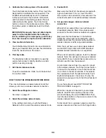
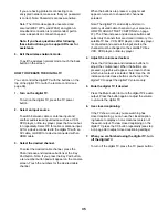
3.  Start the walking belt and adjust the speed.

   Touch the Start button on the screen or press the 

Start button on the console to start the walking 

belt. You can also press the Manual button on the 

console, and then touch the Resume button on 

Summary of Contents for Commercial 2950 NTL22113.0

Page 1: ...uipment Save this manual for future reference www nordictrack com USER S MANUAL ACTIVATE YOUR WARRANTY To register your product and activate your warranty today go to www nordictrackservice com registration CUSTOMER CARE For service at any time go to www nordictrackservice com Or call 1 800 TO BE FIT 1 800 862 3348 Mon Fri 6 a m 6 p m MT Sat 8 a m 12 p m MT Please do not contact the store ...

Page 2: ...T 45 EXPLODED DRAWING 47 ORDERING REPLACEMENT PARTS Back Cover LIMITED WARRANTY Back Cover NORDICTRACK is a registered trademark of ICON Health Fitness Inc This drawing shows the locations of the warning decals If a decal is missing or illegible call the telephone number on the front cover of this manual and request a free replacement decal Apply the decal in the location shown Note The decals may...

Page 3: ...an appropriate outlet see page 22 To avoid overloading the circuit do not plug other electrical devices except for low power devices such as cell phone chargers into the surge suppressor or into an outlet on the same circuit 13 Use only a surge suppressor that meets all of the specifications described on page 22 To purchase a surge suppressor see your local NORDICTRACK dealer call the telephone nu...

Page 4: ...ormed by an authorized ser vice representative only 28 Over exercising may result in serious injury or death If you feel faint if you become short of breath or if you experience pain while exercising stop immediately and cool down 29 Do not store the television in temperatures below 40 F 40 C or above 140 F 60 C Do not operate the television in temperatures below 23 F 5 C or above 90 F 32 C 30 To ...

Page 5: ...tion 810 21 j or your local codes and ordinances 39 Note to CATV system installer This reminder is provided to call the CATV system install er s attention to Article 820 40 of the NEC or your local codes and ordinances that provide guidelines for proper grounding and in par ticular specifies that the cable ground shall be connected to the grounding system of the building as close to the point of c...

Page 6: ...6 ...
Page 7: ...7 all STANDARD SERVICE PLANS ...

Page 8: ...g the treadmill If you have questions after reading this manual please see the front cover of this manual To help us assist you please note the product model number and serial number before contacting us The model number and the location of the serial num ber decal are shown on the front cover of this manual Before reading further please review the drawing below and familiarize yourself with the l...

Page 9: ...er following the key number is the quantity used for assembly Note If a part is not in the hardware kit check to see whether it is preattached Extra parts may be included 8 x 3 4 Screw 5 14 5 16 Nut 9 2 5 16 Star Washer 8 8 10 x 3 4 Screw 6 2 5 16 x 1 3 4 Bolt 3 1 5 16 x 2 Screw 2 4 5 16 x 3 4 Screw 1 4 5 16 x 2 1 4 Bolt 4 1 5 16 x 3 1 4 Screw 88 4 8 x 3 4 Truss Head Screw 24 8 8 x 1 2 Machine Scr...

Page 10: ...uded hex key one adjustable wrench one Phillips screwdriver To avoid damaging parts do not use power tools 1 Go to www nordictrackservice com registration on your computer and register your product activates your warranty saves you time if you ever need to contact Customer Care allows us to notify you of upgrades and offers Note If you do not have Internet access call Customer Care see the front c...

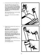
Page 11: ...ove and discard the four indicated Screws C 89 B 84 141 141 90 3 C C A 4 Identify the left Tray Bracket 76 which has an attached wire tie IMPORTANT To avoid damaging the Tray Bracket 76 do not use power tools Attach the left Tray Bracket 76 to the left Upright 84 with two 8 x 1 2 Machine Screws 13 and four 8 Flat Washers 23 IMPORTANT See drawing 4b Make sure that the Tray Bracket is attached with ...

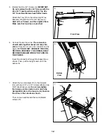
Page 12: ...do not turn one connector and try again IF YOU DO NOT CONNECT THE CON NECTORS PROPERLY THE CONSOLE MAY BECOME DAMAGED WHEN YOU TURN ON THE POWER Insert the connectors through the looped tie as shown Then pull the tie tight and cut off the excess tie 5 6 5 5 76 Tie 79 Front View 76 Wires Bottom View 7 Attach the two Handrails 74 to the Uprights 84 with two 5 16 x 3 1 4 Screws 88 and two 5 16 Star W...

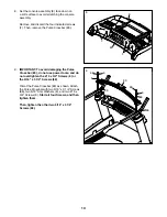
Page 13: ...T To avoid damaging the Pulse Crossbar 80 do not use power tools and do not overtighten the 10 x 3 4 Screws 6 or the 5 16 x 3 1 4 Screws 88 Orient the Pulse Crossbar 80 as shown Attach the Pulse Crossbar with two 5 16 x 3 1 4 Screws 88 two 5 16 Star Washers 8 and two 10 x 3 4 Screws 6 Start all four Screws and then tighten them Then tighten the other two 5 16 x 3 1 4 Screws 88 80 9 8 8 88 88 88 88...

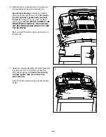
Page 14: ...nd try again IF YOU DO NOT CONNECT THE CONNECTORS PROPERLY THE CONSOLE MAY BECOME DAMAGED WHEN YOU TURN ON THE POWER Next connect the two fan wires not shown on the left side 83 E 10 83 G G 74 11 Attach the console assembly E to the Handrails 74 with four 5 16 x 2 Screws 2 and four 5 16 Star Washers 8 Start all four Screws and then tighten them Be careful not to pinch the wires Insert the wires up...

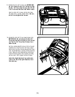
Page 15: ...not confuse the 8 x 3 4 Truss Head Screws with the 8 x 3 4 Screws 5 The 8 x 3 4 Truss Head Screws have flatter heads Set the Left Handrail Top Cover 73 on the left Handrail 74 Start four 8 x 3 4 Truss Head Screws 24 into the Left Handrail Bottom Cover 75 the left Handrail and the Left Handrail Top Cover Slide the Left Handrail Top and Bottom Covers forward against the console assembly E as shown T...

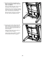
Page 16: ...5 16 x 1 3 4 Bolt 3 and a 5 16 Nut 9 Raise the Storage Latch 56 to a vertical posi tion Then remove and discard the tie H 84 56 3 52 Decal 9 H 14 15 Align the upper end of the Storage Latch 56 with the bracket on the Frame 52 Insert a 5 16 x 2 1 4 Bolt 4 through the bracket This should push a spacer I out of the other end Discard the spacer Attach the Storage Latch 56 with a 5 16 x 2 1 4 Bolt 4 an...

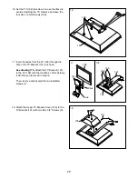
Page 17: ...102 through the hole in the TV Bracket 131 as shown See drawing 17b Attach the TV Bracket 131 to the TV 102 with the four M4 x 12mm Screws 130 that you removed in step 16 Then remove and discard the two indicated screws J 17 17b 131 102 Wires 131 102 130 130 J Hole 18 Attach the Upper TV Bracket Cover 103 to the TV Bracket 131 with two 8 x 3 4 Screws 5 18 103 131 5 ...

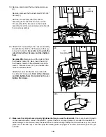
Page 18: ... 78 Next insert the end of the Coaxial Cable into the indicated hole in the Lower TV Bracket Cover 97 and reattach the nut to the Coaxial Cable Attach the Lower TV Bracket Cover 97 with four 8 x 3 4 Screws 5 Start all four Screws and then tighten them Be careful not to over tighten the Screws 20 20b 97 1 E TV Assembly 5 5 21 Make sure that all parts are properly tightened before you use the treadm...

Page 19: ...onnect one end of a 75 ohm CATV cable to the 75 ohm output jack on your external source 2 Plug in the power cord of your external source See your external source user s manual for proper grounding instructions 3 Connect the 75 ohm CATV cable to the 75 ohm ter minal on the treadmill frame near the power cord See the drawing at the left 300 to 75 Ohm Adapter Screwdriver 300 Ohm Flat Wire 75 Ohm Term...

Page 20: ...deo input jack on the TV as shown below HOW TO CONNECT A DVD OR BLU RAY PLAYER OR OTHER DEVICE USING AN HDMI CABLE 1 Connect one end of an HDMI cable to your DVD or Blu ray player or other device 2 Plug in the power cord of your device See your DVD or Blu ray player or other device s user s manual for proper grounding instructions 3 Connect the other end of the HDMI cable to the HDMI input jack on...

Page 21: ...atures above 122 F 50 C or below 14 F 10 C Do not excessively bend or stretch the sensor when using or storing the heart rate monitor To clean the sensor use a damp cloth and a small amount of mild soap Then wipe the sensor with a damp cloth and thoroughly dry it with a soft towel Never use alcohol abrasives or chemicals to clean the sensor Hand wash and air dry the chest strap TROUBLESHOOTING If ...

Page 22: ...s page Plug the power cord into a surge suppressor and plug the surge suppressor into an appropriate outlet that is properly installed and grounded in accordance with all local codes and ordinances The outlet must be on a nominal 120 volt circuit capable of carrying 15 or more amps To avoid overloading the circuit do not plug other electrical devices except for low power devices such as cell phone...

Page 23: ...dmill console offers an array of fea tures designed to make your workouts more effective and enjoyable When you use the manual mode you can change the speed and incline of the treadmill with the touch of a button As you exercise the console will display instant exercise feedback You can also measure your heart rate using the handgrip heart rate monitor or the chest heart rate monitor In addition t...

Page 24: ...ll to its lowest setting When the frame stops moving the treadmill is ready for use Note The console can display speed and distance in either miles or kilometers To find which unit of mea surement is selected see step 4 on page 31 For simplicity all instructions in this section refer to miles HOW TO USE THE TOUCH SCREEN The console features a tablet with a full color touch screen The following inf...

Page 25: ...kout see page 27 To use a set a goal workout see page 28 To use an iFit workout see page 29 To use the equipment settings mode see page 31 To use the sound system see page 32 To use the Internet browser see page 33 To use the main tenance mode see page 33 To use the wireless network mode see page 34 To operate the digital TV see page 35 To use the entertainment mode see page 36 To use the remote c...

Page 26: ... adjust the incline you must first calibrate the incline system see step 4 on page 34 5 Monitor your progress with the displays The console offers sev eral display modes The display mode that you select will determine which workout information is shown To select the desired display mode simply flick or slide the screen You can also view addi tional information by touching the red boxes on the scre...

Page 27: ... off position and unplug the power cord IMPORTANT If you do not do this the treadmill s electrical components may wear prematurely HOW TO USE AN ONBOARD WORKOUT 1 Insert the key into the console See HOW TO TURN ON THE POWER on page 24 2 Select an onboard workout To select an onboard workout touch the runner button on the screen Then select the desired workout The screen will show the name duration...

Page 28: ...ous factors such as your weight In addition if you manu ally change the speed or incline of the treadmill during the workout the number of calories you burn will be affected 4 Monitor your progress with the displays See step 5 on page 26 The screen can also show a profile of the speed and incline settings of the workout 5 Measure your heart rate if desired See step 6 on page 26 6 Turn on the fan i...

Page 29: ...ey from the console See step 8 on page 27 HOW TO USE AN IFIT WORKOUT Note To use an iFit workout you must have access to a wireless network see HOW TO USE THE WIRELESS NETWORK MODE on page 34 An iFit account is also required 1 Insert the key into the console See HOW TO TURN ON THE POWER on page 24 2 Select the main menu See step 2 on page 25 3 Log in to your iFit account If you have not already do...

Page 30: ...of calories you will burn during the work out If you select a competition workout the display will count down to the beginning of the race 5 Start the workout See step 3 on page 27 During some workouts an audio coach may guide you through your workout 6 Monitor your progress with the displays See step 5 on page 26 The screen may also show a map of the trail you are walking or running During a comp...

Page 31: ...e console sync to your local time Then touch the back button on the screen 6 Select an update time To select a time for automatic firmware updates touch the Update Time button and select the desired time Then touch the back button on the screen IMPORTANT You must still unplug the power cord after using the treadmill Set the update time for a time when you normally use the treadmill and will be ava...

Page 32: ...ng master passcode to unlock the console 1985 12 Set a safety screen timeout The console features an automatic screen reset if no buttons are touched or pressed and the walking belt does not move for a set amount of time the console will automatically reset To set the amount of time the console will wait before it automatically resets touch the Safety Screen Timeout button to view a list of times ...

Page 33: ...he workout buttons will not function Note If you have questions after following these instructions go to support iFit com for assistance HOW TO USE THE MAINTENANCE MODE 1 Select the settings main menu See step 1 on page 31 2 Select the maintenance mode In the settings main menu touch the Maintenance button to enter the maintenance mode The mainte nance mode main screen will show infor mation about...

Page 34: ... checkbox is marked with a green checkmark If it is not touch the Wi Fi menu option once and wait for a few seconds The console will search for available wireless networks 4 Set up and manage a wireless network connection When Wi Fi is enabled the screen will show a list of available networks Note It may take several seconds for the list of wireless networks to appear Make sure that the checkbox o...

Page 35: ...reen Touch the numbers for the desired cable channel When the buttons are pressed a graphic will appear on screen to show which channel is selected Note The digital TV can identify and store in memory all valid cable channels in your area see HOW TO ADJUST THE TV SETTINGS on page 37 The Chan increase and decrease buttons will select only channels that are stored in memory If a satellite TV box VCR...

Page 36: ...hannel CH increase or decrease button to select a channel Press the return button to view the previous channel Press the Menu button to view the main menu or to view a previous menu See pages 37 and 38 for infor mation about the menu Press the arrow keys to navigate in the menu Press the OK Enter button to make a selection in the menu Press the Exit button to exit any menu Press the List button to...

Page 37: ...ings and person alize the image settings 3 Adjust the audio settings The Audio menu offers numerous features for adjusting the TV audio output Use the arrow but tons to navigate through the various settings and personalize the audio settings 4 Adjust the channel settings The Channel menu allows you to save channels in the TV memory and select settings for chan nels Note You can only access this me...

Page 38: ...or the clock settings To enter the closed caption submenu highlight Closed Caption and press the Enter button In the closed caption submenu adjust the caption display caption type and the digital preset and style Select Menu Language to change the language used in the menus Select Clock to adjust the TV clock s time zone auto setting time setting day of the week setting and daylight saving time se...

Page 39: ...et place a mat under the treadmill Keep the treadmill out of direct sunlight Do not leave the treadmill in the storage position in temperatures above 85 F 30 C HOW TO MOVE THE TREADMILL Before moving the treadmill fold it as described at the left CAUTION Make sure that the storage latch is locked in the storage position Moving the treadmill may require two people Hold the handrails with both hands...

Page 40: ...t the key is inserted into the console c Check the power switch located on the treadmill frame near the power cord If the switch protrudes as shown the switch has tripped To reset the power switch wait for five minutes and then press the switch back in SYMPTOM The power turns off during use a Check the power switch see drawing c at the left If the switch has tripped wait for five minutes and then ...

Page 41: ...see step 4 on page 34 SYMPTOM The walking belt slows when walked on a Use only a surge suppressor that meets all of the specifications described on page 22 b If the walking belt is overtightened treadmill per formance may decrease and the walking belt may become damaged Remove the key and UNPLUG THE POWER CORD Using the hex key turn both idler roller screws counterclockwise 1 4 of a turn When the ...

Page 42: ...Repeat until the walking belt is centered b If the walking belt slips when walked on first remove the key and UNPLUG THE POWER CORD Using the hex key turn both idler roller screws clockwise 1 4 of a turn When the walk ing belt is correctly tightened you should be able to lift each edge of the walking belt 2 to 3 in 5 to 7 cm off the walking platform Be careful to keep the walking belt centered The...

Page 43: ...or other objects Change the direction or position of the antenna to improve reception Blue Screen If your fitness equipment is located in the fringe area of a TV station where the signal is weak the picture may be of poor quality or a blue screen may appear If the signal is weak it may be necessary to install an exter nal antenna to improve the picture Fading If blocks of the picture are missing t...

Page 44: ...ic Exercise If your goal is to strengthen your cardiovascular system you must perform aerobic exercise which is activity that requires large amounts of oxygen for prolonged periods of time For aerobic exercise adjust the intensity of your exercise until your heart rate is near the highest number in your training zone WORKOUT GUIDELINES Warming Up Start with 5 to 10 minutes of stretch ing and light...

Page 45: ...eft Frame Cover 45 1 Magnet 46 1 Clip 47 1 Reed Switch 48 1 Controller 49 2 8 Star Washer 50 1 Controller Bracket 51 1 Drive Roller Pulley 52 1 Frame 53 4 Tie 54 1 Drive Motor 55 1 Motor Belt 56 1 Storage Latch 57 1 Right Frame Cover 58 2 Rear Foot 59 1 Idler Roller 60 1 Left Rear Cap 61 1 Right Rear Cap 62 1 Motor Hood 63 2 Incline Frame Spacer 64 2 Frame Spacer 65 1 Incline Frame 66 1 Incline Mo...

Page 46: ...ion Bushing 115 2 Cushion Rod Bracket 116 1 Cushion Rod 117 2 Cushion Wheel 118 8 Cushion Plate 119 4 Cushion Spring 120 1 Left Rear Cap 121 1 Right Rear Cap 122 8 Foot Rail Plate 123 8 Right Rear Cap 124 2 Cushion Wheel Stop 125 1 Tray Fan 126 1 Tray Fan Cover 127 1 2 5A Power Supply 128 12 Stand off 129 1 Power Supply Plate 130 4 M4 x 12mm Screw 131 1 TV Bracket 132 2 1 4 x 1 1 2 Screw 133 2 1 4...

Page 47: ... 20 38 44 5 5 5 5 5 5 51 52 17 17 50 5 5 5 5 18 18 13 13 49 19 5 5 20 20 37 11 11 122 123 121 120 37 119 118 118 118 118 119 37 118 118 119 118 118 119 37 124 124 11 122 123 11 122 123 11 122 123 122 122 123 123 122 122 123 123 5 5 11 11 11 87 128 5 48 136 128 128 127 129 128 11 11 EXPLODED DRAWING A Model No NTL22113 0 R0514B ...

Page 48: ...5 5 5 36 36 36 36 5 5 66 65 67 34 35 14 63 15 34 63 64 28 64 35 28 5 5 5 5 5 5 72 71 70 69 68 68 5 5 5 5 116 33 117 115 111 33 112 110 117 115 114 33 110 111 114 113 EXPLODED DRAWING B Model No NTL22113 0 R0514B ...

Page 49: ... 5 8 82 74 75 24 24 74 81 77 88 8 5 5 5 5 6 8 88 2 80 73 77 8 24 24 2 6 135 10 135 10 86 1 76 76 141 32 133 143 145 132 142 142 140 144 137 137 111 32 32 5 138 32 5 86 5 32 86 141 139 138 83 10 135 134 10 135 86 32 23 134 134 134 134 13 5 5 23 23 EXPLODED DRAWING C Model No NTL22113 0 R0514B ...

Page 50: ...50 11 11 11 107 5 106 105 5 5 5 5 5 105 99 99 29 29 104 11 101 11 11 100 96 29 29 29 11 94 11 11 95 95 11 11 29 11 11 107 11 EXPLODED DRAWING D Model No NTL22113 0 R0514B ...

Page 51: ...51 108 109 102 98 16 130 1 1 131 5 5 103 5 97 78 EXPLODED DRAWING E Model No NTL22113 0 R0514B ...

Page 52: ...that specifically set forth above is authorized by ICON ICON is not responsible or liable for indirect special or consequential damages arising out of or in con nection with the use or performance of the product damages with respect to any economic loss loss of property loss of revenues or profits loss of enjoyment or use or costs of removal or installation or other consequential damages of any ki...

Reviews: