background image

22

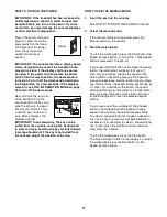
When you select an iFit Live workout, the display

will show the duration of the workout, the distance

you will walk or run, and the approximate number of

calories you will burn. The display may also show

the name of the workout. If you select a competition

workout, the display will count down to the begin-

ning of the race.

Note: Each iFit Live button can also run two demo

workouts. To use the demo workouts, remove the

iFit Live module from the console and press one of

the iFit Live buttons.

5. Start the workout.

See step 3 on page 20.

During some workouts, the voice of a personal

trainer will guide you through your workout. You

can select an audio setting for your personal trainer

(see THE INFORMATION MODE on page 23).

To stop the workout at any time, press the Stop

button. The time will begin to flash in the display.

To resume the workout, press the Start button or

the Speed increase button. The walking belt will

begin to move at the speed setting for the first seg-

ment of the workout. When the next segment of the

workout begins, the treadmill will automatically ad-

just to the speed and incline settings for the next

segment.

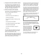
6. Follow your progress with the displays.

See step 5 on page 18.

The My Trail tab will show a map of the trail you

are walking or running or it will show a track and

the number of laps you complete.

During a competition workout, the Competition tab

will show your progress in the race. As you race,

the top line in the matrix will show how much of the

race you have completed. The other lines will show

your top four competitors. The end of the matrix

represents the end of the race.

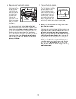
7. Measure your heart rate if desired.

See step 6 on page 19.

8. Turn on the fan if desired.

See step 7 on page 19.

9. When you are finished exercising, remove the

key from the console.

See step 8 on page 19.

For more information about the iFit Live mode, go

to www.iFit.com.

HOW TO USE THE STEREO SOUND SYSTEM

To play music or audio books through the consoleʼs

stereo speakers, you must connect your MP3 player,

CD player, or other personal audio player to the con-

sole through the audio jack below the speakers.

Plug one end of your audio wire into the audio jack on

the console. Plug the other end into a jack on your

MP3 player, CD player, or other personal audio player.

Make sure that the audio wire is fully plugged in.

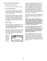
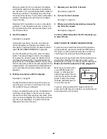
Next, press the play button

on your MP3 player, CD

player, or other personal

audio player. Adjust the vol-

ume on your personal audio

player or press the volume

increase and decrease but-

tons on the console.

If you are using a personal CD player and the CD

skips, set the CD player on the floor or another flat sur-

face instead of on the console.

Decrease

Increase

Summary of Contents for C900 Pro

Page 1: ...e reference QUESTIONS If you have questions or if parts are damaged or missing DO NOT CON TACT THE STORE please contact Customer Care IMPORTANT Please register this product see the limited warranty on...

Page 2: ...30 EXPLODED DRAWING 32 ORDERING REPLACEMENT PARTS Back Cover LIMITED WARRANTY Back Cover This drawing shows the locations of the warning decals If a decal is missing or il legible call the telephone...

Page 3: ...he surge suppressor or into an outlet on the same circuit 12 Use only a surge suppressor that meets all of the specifications described on page 15 To purchase a surge suppressor see your local NORDICT...

Page 4: ...23 Never insert any object into any opening on the treadmill 24 Inspect and properly tighten all parts of the treadmill regularly 25 DANGER Always unplug the power cord immediately after use before c...

Page 5: ...u have questions after read ing this manual please see the front cover of this man ual To help us assist you please note the product model number and serial number before contacting us The model numbe...

Page 6: ...rew 8 4 8 x 1 Screw 25 4 5 16 x 1 Screw 5 4 PART IDENTIFICATION CHART Use the drawings below to identify small parts used for assembly The number in parentheses below each draw ing is the key number o...

Page 7: ...EMBLY Assembly requires two persons Place all parts in a cleared area and remove the packing materials Do not dispose of the packing materials until you finish all assembly steps The underside of the...

Page 8: ...Upright 81 3 81 89 Wire Tie Wire Tie 89 94 81 4 Hold the Left Upright 89 against the Base 94 Be careful not to pinch any wires Insert two 3 8 x 2 3 4 Screws 7 and two 3 8 x 1 1 4 Screws 8 with two 3 8...

Page 9: ...wire tie from the Upright Wire 81 89 82 90 83 5 Wire Tie 81 6 Identify the Left Handrail 88 and hold it near the Left Upright 89 Tie the wire tie in the Left Handrail 88 securely around the end of th...

Page 10: ...e indicated bracket Be careful not to pinch the Upright Wire between the Left Outside Handrail Cover 80 and the bracket Remove and discard the four indicated Screws A 7 89 88 87 4 4 5 5 80 81 Bracket...

Page 11: ...Tighten all four 10 x 3 4 Screws 9 about halfway into the Handrails 87 88 Then slide the Crossbar as far forward as possible and tighten the four Screws 93 88 9 9 9 87 10 Attach the Console Frame 104...

Page 12: ...und Wire 105 and insert the wires into the hole in the console assembly Console Assembly Console Wire Wire Tie 88 81 81 Console Wire 11 Ground Wire 105 Hole 12 Set the console assembly on the Left Han...

Page 13: ...94 until they snap into place 13 83 8 82 94 7 14 Raise the Frame 56 to the position shown Have a second person hold the Frame until step 15 is completed Orient the Storage Latch 53 so that the large...

Page 14: ...rpet place a mat under the treadmill Note Extra hardware may be included Keep the included hex keys in a secure place one of the hex keys is used to adjust the walking belt see pages 26 and 27 15 Atta...

Page 15: ...into a surge suppressor and plug the surge suppressor into an appropriate outlet that is properly installed and grounded in accordance with all local codes and ordinances The outlet must be on a nomi...

Page 16: ...rkouts track your workout re sults race against other runners and access many other features To purchase an iFit Live module at any time go to www iFit com or call the telephone number on the front co...

Page 17: ...adjust the position of the clip HOW TO USE THE MANUAL MODE 1 Insert the key into the console See HOW TO TURN ON THE POWER at the left 2 Select the manual mode If the manual mode is not selected press...

Page 18: ...kout A new segment will appear at the end of each minute The Speed tab will show a profile of the speed settings of the workout The My Trail tab will show a track that represents 1 4 mile 400 m As you...

Page 19: ...The fan features multiple speed settings Press the fan increase or de crease button to select a fan speed or to turn off the fan Note If the fan is on when the walking belt is stopped the fan will tur...

Page 20: ...g for the current segment At the end of each segment a series of tones will sound and the next segment of the profile will begin to flash If a different speed and or incline setting is programmed for...

Page 21: ...ole To insert the iFit Live module see the instructions included with the iFit Live module IMPORTANT To satisfy exposure compliance requirements the antenna and transmitter in the iFit Live module mus...

Page 22: ...you are walking or running or it will show a track and the number of laps you complete During a competition workout the Competition tab will show your progress in the race As you race the top line in...

Page 23: ...when you plug in the power cord press the power switch into the reset position and insert the key into the con sole However when you remove the key the dis plays will remain lit although the buttons...

Page 24: ...in the storage position Moving the tread mill may require two people 1 Hold the frame and one of the handrails and place one foot against a wheel 2 Pull back on the handrail until the treadmill will...

Page 25: ...tch back in SYMPTOM The power turns off during use a Check the power switch see the drawing above If the switch has tripped wait for five minutes and then press the switch back in b Make sure that the...

Page 26: ...the key from the console SYMPTOM The walking belt slows when walked on a Use only a single outlet surge suppressor that meets all of the specifications described on page 15 b If the walking belt is ov...

Page 27: ...l the walking belt is centered b If the walking belt slips when walked on first re move the key and UNPLUG THE POWER CORD Using the hex key turn both idler roller screws clockwise 1 4 of a turn When t...

Page 28: ...al is to strengthen your cardiovascular system you must perform aerobic exer cise which is activity that requires large amounts of oxygen for prolonged periods of time For aerobic ex ercise adjust the...

Page 29: ...lles Stretch With one leg in front of the other reach forward and place your hands against a wall Keep your back leg straight and your back foot flat on the floor Bend your front leg lean forward and...

Page 30: ...solator Spring 42 1 Left Foot Rail 43 1 Caution Decal 44 1 Walking Platform 45 1 Walking Belt 46 2 Belt Guide 47 1 Right Rear Foot 48 4 Cable Tie 49 1 Drive Roller Pulley 50 1 Magnet 51 1 Reed Switch...

Page 31: ...ck 103 1 Console 104 1 Console Frame 105 1 Console Ground Wire 106 2 Console Clamp 107 2 1 4 x 1 1 2 Bolt User s Manual Note Specifications are subject to change without notice For information about o...

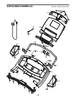
Page 32: ...51 21 35 45 12 2 10 10 48 23 15 34 30 59 61 15 30 34 59 38 39 40 41 14 39 41 39 41 38 39 41 38 38 2 26 26 2 26 2 23 19 46 43 42 44 21 2 41 39 38 39 41 38 39 41 38 14 39 41 38 40 26 2 26 2 34 30 59 26...

Page 33: ...66 10 76 77 74 2 68 75 10 2 73 65 2 2 2 72 74 2 2 2 78 2 62 2 2 2 2 2 58 2 2 2 2 2 68 68 2 2 2 67 67 33 29 69 33 70 16 71 33 33 71 101 32 EXPLODED DRAWING B Model No NTL99010 6 R0312A 33...

Page 34: ...17 17 97 96 33 92 92 77 81 2 33 97 14 14 14 94 22 22 10 28 89 7 13 8 90 7 13 4 86 4 5 81 82 83 8 5 91 7 7 91 31 79 80 2 2 2 2 2 85 88 31 87 37 2 2 84 2 92 14 34 EXPLODED DRAWING C Model No NTL99010 6...

Page 35: ...98 9 93 1 36 27 64 25 25 106 106 104 105 10 2 102 103 2 2 2 2 2 2 1 1 2 99 9 2 1 1 1 1 1 1 1 4 11 4 11 35 EXPLODED DRAWING D Model No NTL99010 6 R0312A...

Page 36: ...y does not extend to freight damage to the product This warranty will automati cally be voided if the product is used as a store display model if the product is purchased or transported outside the US...

Reviews: