background image

8

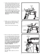
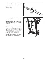
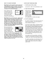
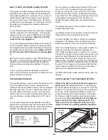
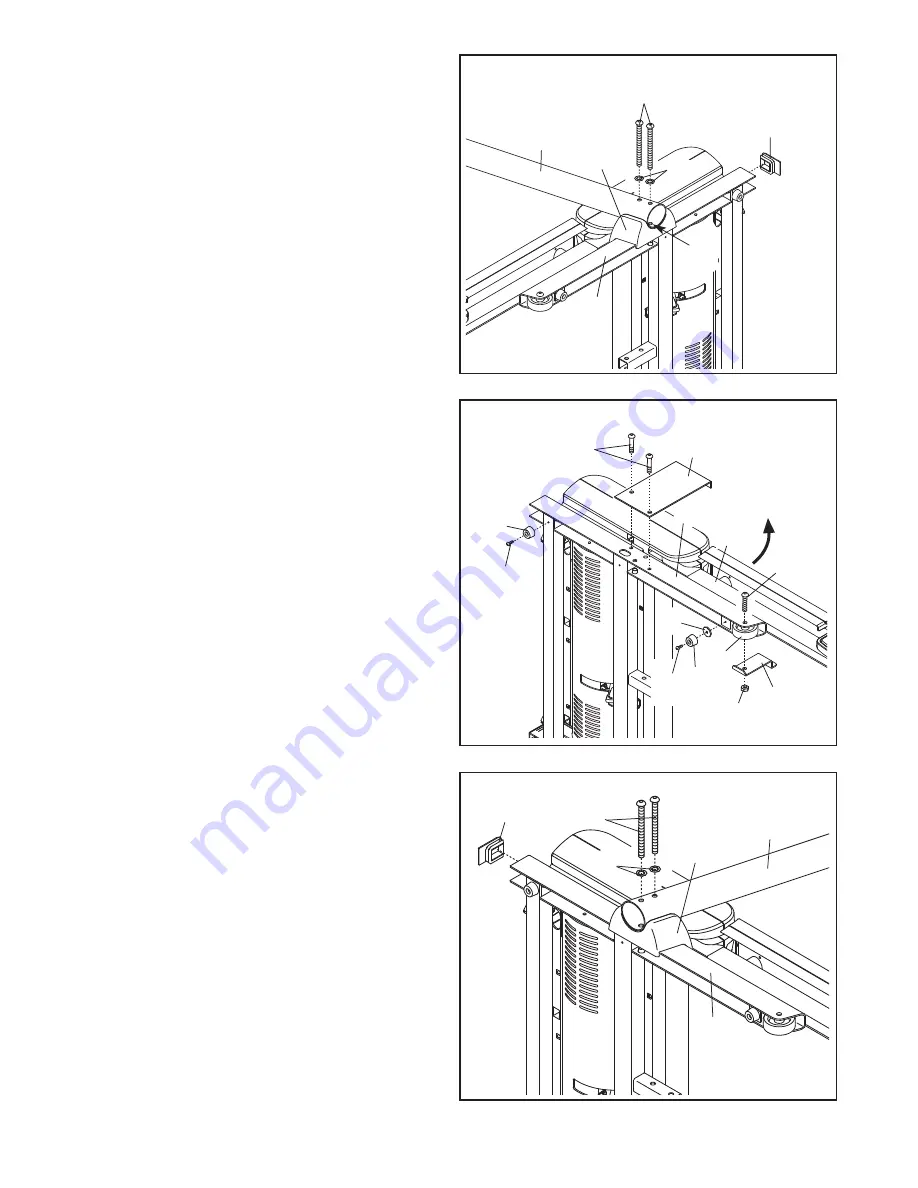
6. Set the Left Upright Spacer (76) on the Base

(83). With the help of a second person, insert
two 3/8” x 5” Bolts (6) with two 3/8" Star
Washers (9) into the Left Upright (74) and set
the Left Upright into the Left Upright Spacer. If
necessary, use a rubber mallet on top of the Left
Upright to make sure that the Upright is fully in-
serted into the Left Upright Spacer. 

Partially tighten the 3/8” x 5” Bolts (6) by turning
them several times; 

do not fully tighten the

Bolts yet.

Press a Base Endcap (77) into the Base (83).

With the help of a second person, tip the tread-
mill so that the Base (83) is flat on the floor.

76

74

6

83

77

6

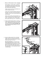
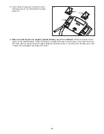
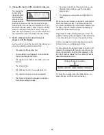
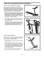
5. With the help of a second person, carefully tip

the treadmill onto its right side. Partially fold the
Frame (56) so the treadmill is more stable; 

do

not fully fold the Frame yet.

Remove and discard the two indicated bolts (A)
and the shipping bracket (B).

Attach a Base Pad (81) to the Base (83) in the
location shown with a #8 x 1" Tek Screw (2) and
a Base Pad Spacer (13). Then, attach another
Base Pad (81) with only a #8 x 1" Tek Screw (2).

Remove the 3/8" Nut (8), the 3/8" x 2" Bolt (4),
and the shipping bracket (C) from the Base (83).
Attach a Wheel (84) with the Bolt and the Nut
that you just removed. 

Do not overtighten the

Nut; the Wheel must turn freely. 

Discard the

shipping bracket.

5

83

B

A

84

56

4

8

C

81

2

81

13

2

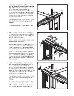
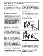
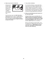
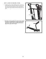
4. Set the Right Upright Spacer (79) on the Base

(83). 

Be careful not to pinch the Upright Wire

(38). 

With the help of a second person, insert

two 3/8” x 5” Bolts (6) with two 3/8" Star
Washers (9) into the Right Upright (78) and set
the Right Upright into the Right Upright Spacer.
If necessary, use a rubber mallet on top of the
Right Upright to make sure that the Upright is
fully inserted into Spacer. 

Partially tighten the 3/8” x 5” Bolts (6) by turning
them several times; 

do not fully tighten the

Bolts yet.

Press a Base Endcap (77) into the Base (83).

79

78

77

6

4

83

38

9

9

Summary of Contents for C2155 NTL07707.0

Page 1: ...if parts are missing PLEASE DO NOT CONTACT THE STORE please contact Customer Care IMPORTANT You must note the product model number and serial number see the drawing above before contacting us CALL TO...

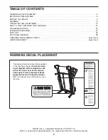
Page 2: ...LIMITED WARRANTY Back Cover 2 NordicTrack is a registered trademark of ICON IP Inc iPod is a trademark of Apple Computer Inc registered in the U S and other countries The decals shown here have been...

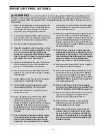
Page 3: ...se an extension cord 12 Use only a single outlet surge suppressor that meets all of the specifications described on page 12 To purchase a surge suppressor see your local NordicTrack dealer or call the...

Page 4: ...he treadmill make sure that the storage latch is fully closed 23 Never insert any object into any opening on the treadmill 24 Inspect and properly tighten all parts of the treadmill regularly 25 DANGE...

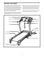
Page 5: ...g the treadmill If you have questions after read ing this manual please see the front cover of this man ual To help us assist you note the product model number and serial number before contacting us T...

Page 6: ...er Assembly requires the included hex keys and your own Phillips screwdriver adjustable wrench and rubber mallet Use the drawings below to identify the assembly hardware The number in parentheses belo...

Page 7: ...that you just removed Do not overtighten the Nut the Wheel must turn freely Discard the shipping bracket 83 4 C 8 2 84 Long Tie Long Tie 78 38 1 Make sure that the power cord is unplugged With the hel...

Page 8: ...olts A and the shipping bracket B Attach a Base Pad 81 to the Base 83 in the location shown with a 8 x 1 Tek Screw 2 and a Base Pad Spacer 13 Then attach another Base Pad 81 with only a 8 x 1 Tek Scre...

Page 9: ...the console as sembly only one side is shown Remove the wire tie from the console wire 5 33 94 Console Assembly Wire Tie 8 9 Remove the long tie from the Upright Wire 38 Have a second person hold the...

Page 10: ...atch 53 to the bracket on the Frame 56 with a 3 8 x 2 Bolt 4 and a 3 8 Nut 8 Note It may be nec essary to move the Frame back and forth to align the Storage Latch with the bracket Lower the Frame 56 s...

Page 11: ...als remove the plastic To protect the floor or carpet place a mat under the tread mill Note Extra hardware may be included Keep the included hex key in a secure place the hex key is used to adjust the...

Page 12: ...tion or break down grounding provides a path of least resistance for electric current to reduce the risk of elec tric shock This product is equipped with a cord having an equipment grounding conducto...

Page 13: ...IT card is included Additional iFIT cards are available separately To purchase iFIT cards at any time go to www iFIT com or call the telephone number on the front cover of this man ual iFIT cards are...

Page 14: ...by carefully taking a few steps backward if the key is not pulled from the console adjust the position of the clip HOW TO USE THE MANUAL MODE 1 Insert the key into the console See HOW TO TURN ON THE P...

Page 15: ...ted The incline setting of the treadmill whenever the incline setting changes Your heart rate Note Your heart rate can be displayed only while you use the handgrip pulse sensor The display can also sh...

Page 16: ...ted the speed of the fan will auto matically increase and decrease as the speed of the walking belt increases and decreases Note If the fan is on when the walking belt is stopped the fan will turn off...

Page 17: ...ng may be programmed for con secutive segments A profile of the speed settings of the workout will appear in the dis play A small arrow below the profile will indicate your progress At the end of the...

Page 18: ...ll automatically adjust to the first speed and in cline settings of the workout Hold the handrails and begin walking During the workout a personal trainer will guide you through the workout You can se...

Page 19: ...wing information will be shown You can select an audio setting if desired When you use an iFIT card a personal trainer will guide you through your workouts If you select the On setting the personal tr...

Page 20: ...is locked in the storage position To protect the floor or carpet from damage place a mat under the treadmill Keep the treadmill out of di rect sunlight Do not leave the treadmill in the stor age posi...

Page 21: ...t It may be neces sary to push the frame forward as you pull the knob to the left Pivot the frame downward and release the latch knob 2 Hold the metal frame firmly with both hands and lower it to the...

Page 22: ...as tripped wait for five minutes and then press the switch back in b Make sure that the power cord is plugged in If the power cord is plugged in unplug it wait for five minutes and then plug it back i...

Page 23: ...insert the key The treadmill will automatically rise to the maximum incline level and then return to the minimum level This will recalibrate the incline system PROBLEM The walking belt slows when walk...

Page 24: ...n the power cord insert the key and run the treadmill for a few minutes Repeat until the walk ing belt is centered b If the walking belt slips when walked on first re move the key and UNPLUG THE POWER...

Page 25: ...goal is to strengthen your cardiovascular system you must perform aerobic exer cise which is activity that requires large amounts of oxygen for prolonged periods of time For aerobic ex ercise adjust t...

Page 26: ...t Frame Ground Wire 40 2 Front Isolator 41 1 Left Foot Rail 42 1 Warning Decal 43 2 Walking Platform Cushion 44 1 Walking Platform 45 1 Walking Belt 46 2 Belt Guide 47 2 Cushion Track 48 2 Frame Space...

Page 27: ...iFIT Universal iPod Connector 103 1 Filter Wire 104 1 Lift Motor Spacer 105 2 8 x 2 Screw 106 1 Right Accessory Tray 107 1 Frame Roller Ground Wire 108 1 5 32 Hex Key 6 Blue Wire 2F User s Manual The...

Page 28: ...20 31 30 31 30 60 59 24 24 29 29 46 46 25 25 25 25 25 41 36 36 49 50 48 43 44 42 45 49 51 55 58 43 56 57 57 48 3 25 25 25 47 16 16 16 47 16 16 16 34 34 12 40 12 40 27 27 80 107 108 28 EXPLODED DRAWING...

Page 29: ...11 11 11 11 72 15 71 37 37 37 1 1 1 12 24 24 68 69 28 24 67 61 66 73 70 103 39 19 19 26 64 63 62 65 32 24 105 105 EXPLODED DRAWING B Model No NTL07707 0 R0907C 29...

Page 30: ...81 2 81 2 81 2 4 84 8 8 84 4 6 9 6 9 21 22 8 8 75 23 23 8 8 77 77 74 83 82 76 79 82 13 81 2 13 104 86 85 52 38 4 8 14 38 78 7 10 7 10 90 88 88 90 93 30 EXPLODED DRAWING C Model No NTL07707 0 R0907C...

Page 31: ...12 92 24 101 91 89 99 1 1 1 1 1 1 1 1 1 1 1 1 1 1 1 5 5 106 98 98 96 95 94 100 1 87 35 102 97 33 33 31 EXPLODED DRAWING D Model No NTL07707 0 R0907C...

Page 32: ...ial damages arising out of or in con nection with the use or performance of the product or damages with respect to any economic loss loss of property loss of revenues or profits loss of enjoyment or u...

Reviews: