Nordic Semiconductor nRF9160 User Manual Download Page 40

Measuring current

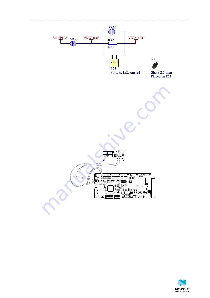
Figure 33: nRF power source

5.2 Using an oscilloscope for current profile

measurement

An oscilloscope can be used to measure the current over a given or continuous time interval and to

capture the current profile.
Before you start, make sure you have prepared the 

DK

 as described in section 

Preparing the development

kit for current measurements

 on page 39.

Follow the steps below to measure the current profile of the nRF9160 DK:

1.

Solder a 0.5 Ω resistor to R97.

Figure 34: Current measurement with an oscilloscope

2.

Connect probes to the pins on connector 

P22

.

3.

Measure the current power profile by measuring the voltage drop over the 0.5 Ω resistor.

5.3 Using a current meter for current measurement

The current drawn by the nRF9160 DK can be measured using a current meter.
Before you start, make sure you have prepared the 

DK

 as described in section 

Preparing the development

kit for current measurements

 on page 39.

To connect the current meter in series with the nRF9160 DK, connect the current meter to the pins on

connector 

P22

.

4418_1216

40

Summary of Contents for nRF9160

Page 1: ...nRF9160 DK Hardware v1 1 0 User Guide 4418_1216 2022 04 19 ...

Page 2: ...5 4 network processor 23 4 8 Buttons slide switches and LEDs 24 4 9 I O expander 25 4 10 External memory 27 4 11 Debug input and trace options 27 4 12 Debug output 28 4 12 1 Connectors for programming external boards 29 4 13 Signal routing switches 30 4 13 1 Interface MCU disconnect switches 31 4 13 2 Switches for UART interface 31 4 13 3 Switches for buttons and LEDs 32 4 13 4 Switches for nRF528...

Page 3: ...5 3 Using a current meter for current measurement 40 6 RF measurements 42 7 Radiated performance of nRF9160 DK 43 Glossary 44 Recommended reading 47 Legal notices 48 4418_1216 iii ...

Page 4: ...l memory on page 27 Switches for I O expander on page 35 Switches for external memory on page 34 July 2020 Updated document title April 2020 Editorial changes March 2020 Updated Recommended reading on page 47 Updated Debug output on page 28 Added Connectors for programming external boards on page 29 October 2019 Updated to match nRF9160 DK v0 9 0 Updated Kit content on page 7 Recommended reading o...

Page 5: ... interfaces on page 17 GPS on page 17 nRF9160 DK board control on page 20 Solder bridge configuration on page 37 Preparing the development kit for current measurements on page 39 RF measurements on page 42 Radiated performance of nRF9160 DK on page 43 December 2018 Updated to match nRF9160 DK v0 8 2 November 2018 Preview DK changed into DK October 2018 First release Previous versions PDF files for...

Page 6: ...F9160 DK see Getting started with nRF9160 DK Key features nRF9160 SiP LTE antenna that supports all bands supported by the SiP Global Positioning System GPS antenna nRF52840 as a board controller and network processor for Bluetooth and IEEE 802 15 4 protocols Buttons switches and LEDs for user interaction I O interface for Arduino form factor plug in modules SEGGER J Link OB Debugger with debug ou...

Page 7: ...layout files The nRF9160 DK PCA10090 comes with a GPS antenna and a SIM card Figure 1 nRF9160 DK kit content Hardware files The hardware design files including schematics Printed Circuit Board PCB layout files bill of materials and Gerber files for the nRF9160 DK are available on the product page 4418_1216 7 ...

Page 8: ...840 as well as external nRF devices fitted on a shield or through a connector to external boards such as the user s own prototypes The interface MCU will automatically detect if external targets are plugged in The PROG DEBUG switch SW10 is used to select nRF9160 or nRF52840 for programming or debugging on board Note that there are significant limitations on using the nRF52840 on the nRF9160 DK For...

Page 9: ... part of the interface MCU If this happens the interface MCU will disconnect and become unresponsive To return to normal operation the DK must be power cycled Your antivirus software might try to scan the MSD part of the interface MCU Some antivirus programs trigger a false positive alert in one of the files and quarantine the unit If this happens the interface MCU will become unresponsive If your...

Page 10: ...umber of other reset routing options available through the use of solder bridges When the interface MCU is disconnected the RESET button is connected to pin 32 nRESET of the nRF9160 SiP The RESET button can be disconnected from the nRF9160 SiP by cutting SB15 When the interface MCU is disconnected shorting SB18 will connect the RESET pin of the Arduino interface to the reset pin of the nRF9160 SiP...

Page 11: ...Operating modes Figure 4 USB detect switch 4418_1216 11 ...

Page 12: ... debugging solution 4 1 Hardware figures The nRF9160 DK hardware drawings show both sides of the PCA10090 Figure 5 nRF9160 DK PCA10090 front view Figure 6 nRF9160 DK PCA10090 back view 4 2 Block diagram The block diagram illustrates the nRF9160 DK functional architecture 4418_1216 12 ...

Page 13: ...rface GPS LNA Analog switches SWF connector SWF connector U FL connector SIM select switch I O Expander Analog switches Current measurement Analog switches for UART External memory Current measurement Figure 7 nRF9160 DK block diagram 4 3 Power supply nRF9160 DK has a flexible and configurable power supply system to allow software development and testing using different power sources and to facili...

Page 14: ...Hardware description Figure 8 nRF9160 DK power supply options 4418_1216 14 ...

Page 15: ...o ensure that only one of the power sources are used on the DK at a time power switches are implemented on each of them as shown in Figure 9 Power sources and switches on page 15 These switches prioritize the supply sources in the following manner 4418_1216 15 ...

Page 16: ...passed by shorting one of the solder bridges as shown in the following table Power source Power switch bypass Voltage level USB connector J6 SB29 5 V External supply P21 SB30 3 0 V 5 5 V VIN 3 5 V P20 SB31 3 0 V 5 5 V Table 2 Bypassing power switch Note Connect only one power source at a time in this case Shorting the solder bridges removes the reverse voltage protection 4 3 1 nRF9160 supply The n...

Page 17: ...ise Amplifier LNA with integrated filters that amplify and filter the signal before it is fed to the GPS RF port on the nRF9160 DK An external active GPS antenna can be connected to J2 When using an external antenna the LNA should be disabled The relation between the connectors radios and antennas are the following J1 Connector with a switch for the LTE antenna A1 J2 Connector for an external GPS ...

Page 18: ...irmware used in the nRF9160 supports GPS The Molex patch antenna achieves the highest gain when placed horizontally on a surface x y facing the z axis since it can receive all propagated GPS signals A lower gain will be experienced if the patch antenna is mounted on a surface is at an angle with the horizontal surface Figure 12 GPS connected to the nRF9160 4 6 GPIO interfaces Access to the nRF9160...

Page 19: ...witches and LEDs For more information see Buttons slide switches and LEDs on page 24 P0 17 P0 18 P0 19 P0 21 P0 22 P0 23 P0 24 COEX0 COEX1 and COEX2 Used to connect nRF9160 to the nRF9160 DK board control on page 20 P0 26 P0 27 P0 28 and P0 29 Used as the primary UART connection to the interface MCU For more information see Virtual COM port on page 8 P0 11 P0 12 P0 23 and P0 25 Used for external m...

Page 20: ...etails on which GPIOs on the nRF9160 DK can be routed by these analog switches see the following table Name nRF52 control GPIO Hardware default nRF9160 GPIO External1 Default Optional P1 14 0 P0 26 P6_pin6 D19 VCOM0_RTS P0 27 P6_pin7 D20 VCOM0_CTS P0 28 P6_pin8 D21 VCOM0_TXD nRF91_UART1 nRF91_APP1 P0 29 P24_pin4 D22 VCOM0_RXD P1 12 1 P0 01 P3_pin2 D1 VCOM2_RXD P0 00 P3_pin1 D0 VCOM2_TXD P0 15 AIN2...

Page 21: ...1 P6_pin1 D14 P25_pin12 TRACECLK nRF52_P0 22 P0 22 P6_pin2 D15 P25_pin14 TRACEDATA0 3 nRF52_P1 04 nRF_IF3 5_CTRL nRF91_TRACE P0 23 P6_pin3 D16 P25_pin16 TRACEDATA1 3 nRF52_P1 02 P1 10 0 GPS_EN P24_pin1 COEX0 nRF52_P1 13 COEX1 P24_pin2 COEX1 nRF52_P1 11 nRF_IF6 8_CTRL nRF91_COEX COEX2 P24_pin3 COEX2 nRF52_P1 15 nRF_IF9_CTRL P0 16 0 P0 24 P6_pin4 D17 P25_pin28 TRACEDATA2 3 nRF52_P0 18_Reset P0 14 0 ...

Page 22: ... controller Default The default connection for the nRF9160 GPIO if the nRF52 control GPIO pins are not driven Hardware default logic level Optional The optional connection for the nRF9160 GPIO if the nRF52 control GPIO pins are driven to the opposite logic level than the hardware default The setup described as Default in the table above is active if all the GPIOs on nRF52840 listed as nRF52 contro...

Page 23: ...TRACEDATA0 3 CLK U7 nRF91_UART1_CTRL U6 nRF91_UART2_CTRL P25 GPIO UART DEFAULT CFG U10 U11 BUTTONx_CTRL x 1 4 USB PINs See Board Control Routing table Figure 16 nRF9160 DK board control Since this firmware in the nRF52840 SoC decides the nRF9160 DK behavior it is vital that it is always present in the nRF52840 SoC If it is accidentally erased or firmware affecting the use of the key nRF52840 GPIOs...

Page 24: ... Buttons slide switches and LEDs The nRF9160 DK has four LEDs two buttons and two switches for simple user interaction By default they are connected to nRF9160 GPIOs as shown in the following table To change default nRF9160 GPIO connections see nRF9160 DK board control on page 20 Part GPIO LED 1 P0 02 LED 2 P0 03 LED 3 P0 04 LED 4 P0 05 Button 1 P0 06 Button 2 P0 07 Switch 1 P0 08 Switch 2 P0 09 T...

Page 25: ...er transistors and LEDs are fed from a separate 3 0 V domain Therefore LED current will not be drawn from nRF9160 GPIOs or the nRF9160 supply Figure 18 Buttons and switches Figure 19 LEDs 4 9 I O expander The nRF9160 DK has an I O expander that can optionally be used to interface the LEDs slide switches and buttons The connection of each component is controlled by the nRF52840 SoC using analog swi...

Page 26: ...ble 6 nRF9160 I O expander interface The following table shows the I O expander connections Component I O expander pin LED 1 I O_EXP_IO4 LED 2 I O_EXP_IO5 LED 3 I O_EXP_IO6 LED 4 I O_EXP_IO7 Switch 1 I O_EXP_IO2 Switch 2 I O_EXP_IO3 Button 1 I O_EXP_IO0 Button 2 I O_EXP_IO1 Table 7 nRF9160 I O expander connections Figure 20 I O expander 4418_1216 26 ...

Page 27: ...GPIO of choice The WP and HOLD pins of the external memory are available only on test points TP55 and TP56 and to use these wires can be strapped form the test points to the GPIOs of choice GND 4 VCC 8 CS 1 SIO0 SI 5 SIO2 WP 3 SCLK 6 SIO3 RESET 7 SIO1 SO 2 U37 MX25R6435FZNIL0 C84 100nF VDD SCK CS MOSI MISO WP RESET MEMORY EXT_MEM R110 100k EXT_MEM_CS EXT_MEM_WP EXT_MEM_RESET EXT_MEM_MISO EXT_MEM_M...

Page 28: ...ll not be available for application firmware use during trace Note Connectors P18 and P25 overlap and share the same footprint GPIO Trace P0 21 TRACECLK P0 22 TRACEDATA 0 P0 23 TRACEDATA 1 P0 24 TRACEDATA 2 P0 25 TRACEDATA 3 Table 9 nRF9160 trace interfaces 4 12 Debug output The nRF9160 DK supports programming and debugging external boards with Nordic SoCs and SiPs To debug an external board with ...

Page 29: ...the voltage level of the external board matches the VDD of the nRF9160 DK P20 can also be used as a debug out connector to program shield mounted targets For both P19 and P20 the interface MCU will detect the supply voltage on the mounted shield and program debug the target If the interface MCU detects target power on both P19 and P20 it will program debug the target connected to P19 by default If...

Page 30: ...ge supply from the external target used as voltage detect input to the interface MCU 4 SWD1_SWDIO Serial Wire Debug SWD data line 5 SWD1_SWDCLK SWD clock line 6 SWD1_SWO Serial Wire Output SWO line 7 SWD1_RESET Reset line 8 N C Not used 9 VIN3 5V Voltage supply 9 VDD_HV Used for current measurement 10 VDD_HV Used for current measurement 12 VIO_REF GPIO voltage reference input 13 ID Board ID resist...

Page 31: ...using the switches shown in the schematics For more information see Performance measurement mode on page 10 Figure 24 Signal interface switches 4 13 2 Switches for UART interface Two UART interfaces are routed between the interface MCU and the nRF9160 SiP These can be controlled individually 4418_1216 31 ...

Page 32: ... connect and disconnect signals to control buttons switches and LEDs The analog switches select if the LEDs buttons and switches should be connected directly to the nRF9160 GPIO or to an I O expander See I O expander on page 25 for more information The switches are controlled by the nRF52840 SoC which contains firmware from Nordic Semiconductor 4418_1216 32 ...

Page 33: ...trol 4 13 4 Switches for nRF52840 interface Four analog switches control the routing of signals between the nRF9160 SiP and the nRF52840 SoC There are ten signals that can be routed between the devices seven GPIOs and three COEX pins 4418_1216 33 ...

Page 34: ... 27 nRF52840 interface switches 4 13 5 Switches for external memory Two analog switches are used to control the signals between the nRF9160 DK and the external memory The switches are controlled by P0 19 of nRF52840 4418_1216 34 ...

Page 35: ... I O expander 4 14 SIM and eSIM The nRF9160 DK is designed to support both regular SIM and Embedded SIM eSIM For this purpose it has a pluggable SIM card socket J5 that takes a nano sized SIM 4FF and a non populated footprint for an eSIM MFF2 Using the SIM socket is the default If an eSIM is soldered on to the DK switch SW7 can be used to select the eSIM Connector P28 can be used to connect and mo...

Page 36: ...s These pins are routed to nRF52840 for use when nRF52840 is used as a network processor These signals are also available on connector P24 In addition COEX0 is used to enable the GPS LNA of the nRF9160 DK RF control interface The nRF9160 DK has an interface allowing the modem to control external RF applications such as antenna tuner devices There are three MIPI RFFE interface pins namely VIO SCLK ...

Page 37: ... SD card reader J8 not populated by default SB3 Closed Cut to disconnect RTS signal from the nRF52840 SoC SB4 Closed Cut to disconnect CTS signal from the nRF52840 SoC SB5 Closed Cut to disconnect RXD signal from the nRF52840 SoC SB6 Closed Cut to disconnect TXD signal from the nRF52840 SoC SB7 Closed Cut to disconnect the 3 0 V USB supply from the interface MCU U4 SB8 Closed Cut to disconnect SWD...

Page 38: ...wer supply of the external device when using the Debug out connector P19 SB25 Open Short to bypass the USB detect switch Q7 SB26 Closed Cut to permanently disable SHIELD DETECT feature SB27 Open Short to permanently enable the SHIELD DETECT feature SB28 Open Short to supply VDD to bottom UART debug connector SB29 Open Short to bypass the USB supply switch U24 SB30 Open Short to bypass the external...

Page 39: ...ply Instead the DK should be powered by connecting a power supply to connector P21 For more information on measuring see sections Using an oscilloscope for current profile measurement on page 40 and Using a current meter for current measurement on page 40 5 1 Preparing the development kit for current measurements To measure the current consumption of the SiP you must first prepare the DK 1 Remove ...

Page 40: ...f the nRF9160 DK 1 Solder a 0 5 Ω resistor to R97 Figure 34 Current measurement with an oscilloscope 2 Connect probes to the pins on connector P22 3 Measure the current power profile by measuring the voltage drop over the 0 5 Ω resistor 5 3 Using a current meter for current measurement The current drawn by the nRF9160 DK can be measured using a current meter Before you start make sure you have pre...

Page 41: ...ed high dynamic range ampere meter for the best and most reliable measurements Current range switching in the current meter may affect the power supply to the nRF9160 DK High speed and bandwidth are required to detect rapid changes in the current consumption in the nRF9160 DK 4418_1216 41 ...

Page 42: ...ed to the onboard antenna The insertion loss in the adapter cable is approximately 0 5 1 dB An adapter is available Murata part no MXHS83QE3000 with a standard SMA connection on the other end for connecting instruments the adapter is not included in the kit When connecting the adapter the internal switch in the SWF connector will disconnect the onboard antenna and connect the RF signal from nRF916...

Page 43: ...ds The average performance of the LTE antenna mounted on the nRF9160 DK is shown in the table below The LTE antenna also supports other frequency ranges but it is not optimized for operating on these frequency bands Band Average return loss dB Average efficiency 3 13 5 62 0 4 7 1 47 1 13 8 5 58 5 20 10 5 73 8 Table 14 Antenna performance versus radio band The 2 4 GHz antenna on the nRF9160 DK is o...

Page 44: ...nline FIDO A bundle of hardware and software modules serving as a tracing interface between traced device s and user application General Purpose Input Output GPIO A digital signal pin that can be used as input output or both It is uncommitted and can be controlled by the user at runtime Global Positioning System GPS A satellite based radio navigation system that provides its users with accurate lo...

Page 45: ...es a public REST API that can be used for building IoT solutions See nRF Cloud nrfcloud com Operational Amplifier op amp A high gain voltage amplifier that has a differential input and usually a single output Printed Circuit Board PCB A board that connects electronic components Receive Data RXD A signal line in a serial interface that receives data from another device Request to Send RTS In flow c...

Page 46: ...that transmits data to another device Universal Asynchronous Receiver Transmitter UART A hardware device for asynchronous serial communication between devices Universal Integrated Circuit Card UICC A new generation SIM used in UE for ensuring the integrity and security of personal data Universal Serial Bus USB An industry standard that establishes specifications for cables and connectors and proto...

Page 47: ...nsult other documents Nordic documentation Getting started with nRF9160 DK nRF9160 Product Specification nRF9160 Modem Firmware Release Notes included in the latest nRF9160 modem firmware nRF Connect SDK documentation nRF91 AT Commands Reference Guide nRF Connect Programmer 4418_1216 47 ...

Page 48: ...right to make corrections enhancements and other changes to this document without notice Life support applications Nordic Semiconductor products are not designed for use in life support appliances devices or systems where malfunction of these products can reasonably be expected to result in personal injury Nordic Semiconductor ASA customers using or selling these products for use in such applicati...

Reviews: