background image


4 Commissioning


B 1050 en-1819 


67 


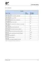
4.11.2  Optional 


Checklist 

Subject of test 

Date 

checked: 

Information 

see Section 

Option R, WX, FAN: 
Is the direction of rotation specified and checked? 


4.9 

Option D and ED: 
Is the torque support correctly fitted? 


3.18 

Option AS, FAN: 
Are contact guards fitted to rotating components? 


3.21 

Option FAN, CS2: 
Is an adequate supply of air ensured? 


4.4 

Option CS1, CC: 
Is the cooling water connected to the cooling unit or the cooling 

coil and open? 


4.5 

Option CS1, CS2: 
Is the cooling unit connected to the gear unit? 


4.6 

Option: LC, LCX: 
Has the pressure switch been functionally connected? 


4.3 

Option PT100: 
Has the temperature monitor been functionally connected? 


4.8 

Option AS: 
Has the shrink disk connection been checked for slippage? 


3.10.2 

Brake option: 
Is the brake correctly adjusted? 


3.20 

Option MT: 
Is the belt correctly tensioned? 


3.13 

Option WX: 
Has the speed monitor been functionally connected? 


4.9 

Table 11: Optional checklist for commissioning 


Pos: 150 /Anleitungen/Getri ebe/5. Inspekti on und War tung/5. Inspektion und Wartung @ 23\mod_1531828817835_388.docx @  2434012  @  1 @ 1 


Summary of Contents for B 1050 Series

Page 1: ...B 1050 en Industrial gear units Operating and Assembly Instructions...

Page 2: ...a and permissible conditions at the installation site must be complied with 3 Transport storage Information regarding transport storage and correct handling must be complied with 4 Installation The de...

Page 3: ...trial gear units Version list Title Date Order number Remarks B 1050 January 2013 6052902 0213 B 1050 September 2014 6052902 3814 General corrections B 1050 April 2015 6052902 1915 General corrections...

Page 4: ...document must be provided to all users in a suitable form Any editing or amendment or other utilisation of the document is prohibited Pos 6 Allgemei n Allgemei ng ltige Modul e H erausgeber 0 mod_1325...

Page 5: ...Publisher B 1050 en 1819 5...

Page 6: ...9 3 9 Motor Option IEC NEMA 31 3 10 Gear unit with hollow shaft Option A EA 34 3 10 1 Hollow shaft with fastening element Option B 35 3 10 2 Hollow shaft with shrink disc element Option S 36 3 11 Flan...

Page 7: ...ED 76 5 2 9 Piping 76 5 2 9 1 Piping Option LC LCX OT 76 5 2 9 2 Hose lines Option LC LCX CS1 CS2 OT 76 5 2 10 Oil filter Option CS1 X CS2 X LC LCX 77 5 2 11 Bearings is the output flange Option VL2 3...

Page 8: ...alignment belt drives 42 Figure 16 Cooling cover with cooling coil fitted schematic diagram 43 Figure 17 Industrial gear unit with CS1 X and CS2 X cooling systems 44 Figure 18 Hydraulic plan of indus...

Page 9: ...t off speeds SK 5 17 SK 11 17 64 Table 10 Obligatory checklist for commissioning 66 Table 11 Optional checklist for commissioning 67 Table 12 Service and Maintenance Intervals 69 Table 13 Disposal of...

Page 10: ...instructions for these components must be observed If geared motors are used compliance with the Motor Operating Manual is also necessary If you do not understand the contents of this Operating Manual...

Page 11: ...ation must be complied with in particular DANGER Explosion hazard Serious injury and material damage due to explosion are possible Use in explosion hazard areas is prohibited WARNING Injury to persons...

Page 12: ...ion regulations Tighten the driven elements or secure the parallel keys before switching on Do not make any structural modifications Do not remove any safety devices If necessary wear hearing protecti...

Page 13: ...is recommended that repairs to NORD products are carried out by the NORD Service department Pos 23 Anl eitungen Getriebe 1 Hinweise Wei ter e U nterlagen 3 mod_1368693112418_388 docx 65889 2 1 1 6 Oth...

Page 14: ...507 SK 9207 SK 9307 SK 9217 SK 9407 SK 9507 SK 10207 SK 10307 SK 10217 SK 10407 SK 10507 SK 11207 SK 11307 SK 11217 SK 11407 SK 11507 SK 12207 SK 12307 SK 12407 SK 12507 SK 13207 SK 13307 SK 13407 SK...

Page 15: ...Fan X R Backstop X X FK Collar flange X S Shrink disc X X F1 Drive flange X V Solid output shaft X H H66 Covering cap as contact guard X X VL Reinforced bearings X IEC Standard IEC motor mounting X V...

Page 16: ...B1050 B2050 30 mod_1552914035630_388 docx 2510809 1 Certain versions options can only be used for particular gear unit sizes or configurations Figure 1 MAXXDRIVE XT 2 stage helical bevel gear unit Po...

Page 17: ...e an additional eyebolt attached to the motor this must not be used Only the four ring bolts provided may be used for transporting the gear unit CAUTION Slipping hazard Transport damage to the gear un...

Page 18: ...050 28 mod_1551451615952_388 docx 2494466 3 1 3 1 1 Standard gear units Gear units may only be transported with lifting ropes and chains or lifting straps at an angle of 90 to 70 to the horizontal Leg...

Page 19: ...2 with motor adapter Gear units with motor adapters may only be transported with lifting ropes and chains or lifting straps at an angle of 90 to 70 to the horizontal The ring bolts on the motor must...

Page 20: ...belt drives Gear units with V belt drives may only be transported with lifting ropes and chains or lifting straps at an angle of 90 to 70 to the horizontal The ring bolts on the motor and the motor br...

Page 21: ...1 3 1 4 with V belt drive Agitator version gear units may only be transported with lifting ropes and chains or lifting straps at an angle of 90 to 70 to the horizontal The ring bolts on the motor mus...

Page 22: ...base frame Gear units on a motor swing base or base frame may only be transported with lifting ropes and chains or lifting straps at an angle of 90 to 70 to the horizontal Only use the attachment poin...

Page 23: ...D recommends the long term storage option With the long term storage option and the use of the measures listed below storage for up to 2 years is possible As the actual influences on the unit greatly...

Page 24: ...issioning The VCI concentrate may remain in the gear unit Lubricant quantities and types must be filled according to the details on the type plate Pos 47 Anl eitungen Getriebe 3 Montage Lager ung Vorb...

Page 25: ...e data NOTICE Gear unit damage The type plate must be checked and the gear unit may only be commissioned if It has been ensured that the gear unit type all technical data and labelling conform to the...

Page 26: ...type plate Pos 50 Anl eitungen Getriebe 3 Montage Lager ung Vorberei tung Aufstellung Pr fung der Baufor m B1050 17 mod_1493037409736_388 docx 2342347 2 1 3 6 Checking the version NOTICE Gear unit da...

Page 27: ...e shafts and flange surfaces before assembly Information Oil filling Gear units and geared motors are not filled with oil as standard when delivered from the factory For filling details of the type an...

Page 28: ...ve substances which attack metal lubricants or elastomers are present in the area surrounding the installation site or are subsequently expected during operation In case of doubt please contact Getrie...

Page 29: ...ry to persons If the foundation or the fastening of the gear unit is not adequately dimensioned the gear unit may detach fall down or rotate in an uncontrolled manner The foundation and the gear unit...

Page 30: ...g masonry bolts or base blocks appropriate recesses must be provided in the base Tensioning bars must be cast into the concrete base in their aligned state Bolts with a minimum quality of 8 8 must be...

Page 31: ...ly rotating parts when installing and servicing couplings Secure the drive against accidental start up The operating and assembly instructions for the coupling must be observed The maximum permitted m...

Page 32: ...max1 mm 615 615 Weight kg 1500 1500 1 see Figure 8 for maximum permitted X dimension Table 2 Transnorm motor weights NORD must be consulted if the values stated in the table are exceeded 1 Centre of...

Page 33: ...haft end of the motor must be adjusted so that it is parallel with the face of the coupling Figure 9 Fitting the coupling to the motor shaft 4 Secure the coupling half with the threaded pin The thread...

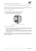
Page 34: ...ive lubricant to the points described before fitting e g Nord Anti Corrosion Part No 089 00099 Excess grease or anti corrosion agent may escape after assembly and may drip off Clean these points on th...

Page 35: ...o solid shafts with and without a shoulder using the fastening element The screw of the fastening element must be tightened with the appropriate torque 7 4 Torque values Assembly Description 1 Fasteni...

Page 36: ...t the gear unit with a hammer If the tensioning bolts of the shrink disc are tightened without the solid shaft inserted the hollow shaft may be permanently deformed Do not tighten the bolts if the sol...

Page 37: ...ushing the solid shaft of the machine must be greased in the area which will later come into contact with the bushing in the hollow shaft of the gear unit Figure 12 It is essential that the tensioning...

Page 38: ...rnal ring does not detach from the inner ring after approx one turn of all screws the external ring can be released with the aid of the push off thread For this the required number of tensioning bolts...

Page 39: ...unit must be obtained from the specific dimension sheet for the order Pos 70 Anl eitungen Getriebe 3 Montage Lager ung Vorberei tung Aufstellung Motorschwing en B1050_B2050 28 mod_1551190965979_388 do...

Page 40: ...ry to persons Risk of injury due to rotating parts and crushing Before starting maintenance and adjustment work it must be ensured that all components of the machine are in a safe position and that th...

Page 41: ...e of the tapered bushing of the pulley 3 Insert the tapered bushing in the hub and bring all connecting holes into alignment Half threaded holes must be opposite half smooth holes 4 Lightly oil studs...

Page 42: ...cylindrical screws 2 Tapered bushing 3 V belt pulley Figure 14 V belt pulley disassembled assembled Legend 1 Axle shaft 2 Belt 3 Belt pulley I Aligned pulleys on parallel axis shafts II Axial displace...

Page 43: ...e of the pipe thread can be obtained from the specific dimension sheet for the order Remove the drain plug from the screw neck prior to assembly to avoid any contamination of the cooling system The sc...

Page 44: ...1552924402092_388 docx 2511145 1 NOTICE Gear unit damage The separate manufacturer s documentation must be observed for assembly Connect the cooling system as shown in Figure 17 In consultation with N...

Page 45: ...2 Pump 3 Heat exchanger 4 Cooling system pressure connection 5 Temperature monitor PT100 6 Cooling water connection Figure 18 Hydraulic plan of industrial gear units with CS1 X and CS2 X cooling syst...

Page 46: ...ear units with lubricant circulation These are already installed on the gear unit on delivery and all lines are correctly connected The flange pump is driven via the gear unit drive shaft Motor pumps...

Page 47: ...stallation upwards or downwards are permissible For helical gear units with motor adapters the torque support is located opposite to the motor adapter Explanation 1 Fork head with bolt 2 Threaded bolt...

Page 48: ...is not ensured This may result in severe material damage and personal injury Adjust the brake as described in the operating instructions before commissioning The brake is supplied in the closed condi...

Page 49: ...lements such as belt drives chain drives shrink disks fans and couplings must be fitted with contact protection The drive unit must be secured against accidental start up while the cover caps are remo...

Page 50: ...device Pos 97 Anl eitungen Getriebe 3 Montage Lager ung Vorberei tung Aufstellung Naben auf Getriebewellen_04 B1050 30 mod_1552980686188_388 docx 2511533 1 Drive and driven elements must only apply f...

Page 51: ...nleitungen Getri ebe 3 M ontage Lagerung Vorbereitung Aufstell ung Antriebskupplung_05 Fl ssig keitskupplung B1050 B2050 30 mod_1552982791903_388 docx 2511831 4 1 3 22 1 2 Turbo coupling WARNING Injur...

Page 52: ...ssioning The switch must be connected to the evaluation electronics by the operator Information Turbo couplings As standard turbo couplings are usually supplied filled with oil Pos 103 Anleitungen Get...

Page 53: ...be 3 M ontage Lagerung Vorbereitung Aufstell ung Sensori kzur Getri ebe ber wachung_03 B1050 B2050 30 mod_1552986887038_388 docx 2512465 1 NOTICE Sensors The following points must be observed for the...

Page 54: ...ling with Without Industrial gear units X Primary gear unit Option WG X Auxiliary gear unit Option WX X Connecting flange Option WX X Turbo coupling X Oil tank Option OT X Table 6 Oil spaces as delive...

Page 55: ...filled with grease Re greasing is carried out via the conical grease nipple Explanation 1 Bearing cover 1 2 Grease filled gap 3 Conical grease nipple 4 Bearing cover 2 Figure 24 Testing a Taconite se...

Page 56: ...od_1552991167384_388 docx 2513349 1 All gear units equipped with lubricant circulation are usually equipped with a pressure switch to monitor the pump function The connection of the pressure switch an...

Page 57: ...be damaged by overheating An adequate supply of air must be ensured by means of a minimum free space of 30 ahead of the air intakes The air inlet grille and the fan blades must be kept clean For ribbe...

Page 58: ...iments is recommended as a coolant The hardness of the water must be between 1 dH and 15 dH the pH value must be between pH 7 4 and pH 9 5 No aggressive liquids may be added to the coolant The coolant...

Page 59: ...erature and the flow rate must be checked and ensured by the operator The maximum permissible cooling water inlet temperature is defined during the planning phase and can be found in the order data If...

Page 60: ...r the oil temperature Pos 133 Allgemein Allgemeing ltig e Module Seitenumbr uch kompakt 13 mod_1476369695906_0 docx 2265495 Pos 134 Anleitungen Getri ebe 4 Inbetriebnahme Temperatur berwachung_01 B105...

Page 61: ...r direction of rotation are available for attachment to the gear unit For auxiliary gear units Option WX the backstop is used for freewheeling in order to allow the gear unit to run at low speeds e g...

Page 62: ...8 56 112 1759 SK 6507 4 125 445 2740 SK 7207 2 7 1 25 400 SK 7307 2 28 315 430 15 25 624 SK 7407 3 28 50 1012 56 100 1636 SK 7507 4 112 400 1759 SK 8207 2 8 28 400 SK 8307 3 32 5 355 430 20 28 624 SK...

Page 63: ...07 3 22 4 112 320 12 5 28 352 SK 12407 3 31 5 45 544 50 71 888 SK 12507 4 80 400 1136 SK 13207 2 5 6 20 250 SK 13307 2 22 4 112 320 12 5 28 352 SK 13407 3 31 5 45 544 50 71 886 SK 13507 4 80 400 1136...

Page 64: ...K 8217 2 6 8 451 SK 7217 SK 8217 2 9 13 697 SK 7217 SK 8217 2 16 20 1136 SK 9217 SK 11217 2 6 8 352 SK 9217 SK 11217 2 9 13 545 SK 9217 SK 11217 2 16 21 887 Table 9 Backstop lift off speeds SK 5 17 SK...

Page 65: ...whether the marking 3 10 2 Hollow shaft with shrink disc element Option S shows a relative movement of the hollow shaft of the gear unit and the machine shaft After this the cover must be re fitted 3...

Page 66: ...form to the specifications 3 5 Does the required configuration conform with the actual installation 7 2 Has the correct oil level for the version been checked 5 2 6 Has the vent been fitted and activa...

Page 67: ...cooling coil and open 4 5 Option CS1 CS2 Is the cooling unit connected to the gear unit 4 6 Option LC LCX Has the pressure switch been functionally connected 4 3 Option PT100 Has the temperature monit...

Page 68: ...il water cooler Option CS2 Service the oil air cooler Brakes check for wear Couplings Service the drive and output couplings Standstill Storage 6 months Regularly check the protective coating on unpai...

Page 69: ...operating hours but at least every 2 years Higher temperatures reduce the oil change intervals Replace shaft sealing rings if worn 5 2 5 Oil change the interval is double for filling with synthetic pr...

Page 70: ...Personal injury due to rapidly rotating machine components Installation and maintenance work must only be performed when the gear units are at a standstill The drive must be isolated and secured to p...

Page 71: ...f the rubbing sealing lip is therefore normal and is not due to leakage Pos 158 Anleitungen Getri ebe 5 Inspekti on und War tung Laufger usche B1050_B2050 17 mod_1493116809037_388 docx 2343006 3 1 5 2...

Page 72: ...lip increases and a measurable leakage with dripping oil occurs The shaft sealing ring must then be replaced The space between the sealing lip and the protective lip must be filled approximately 50 wi...

Page 73: ...n the type plate or the appropriate quantity of oil must be drained off If possible filling should be carried out via the vent position The positions of the oil measuring device the vent and the oil d...

Page 74: ...er and lower marking Figure 28 Checking the oil level with an oil dip stick Pos 171 Anleitungen Getri ebe 5 Inspekti on und War tung lstand_07 lstandsbeh lter B1050 B2050 31 mod_1553009462714_388 docx...

Page 75: ...ng_03 Cellul osefilter_01 B1050 B2050 31 mod_1553011477724_388 docx 2514402 4 1 5 2 7 2 Cellulose filter Option EF Pos 176 Anleitungen Getri ebe 5 Inspekti on und War tung Be und Entl ftung_04 Cellul...

Page 76: ...n Getri ebe 5 Inspekti on und War tung Leitung en_01 B1050 B2050 31 mod_1553070251385_388 docx 2514650 3 1 5 2 9 Piping Pos 182 Anleitungen Getri ebe 5 Inspekti on und War tung Leitung en_02 Verrohrun...

Page 77: ...one year The filter element must be replaced immediately if the contamination indicator triggers Refer to the relevant manufacturer s documentation for further information Pos 189 Anleitungen Getri e...

Page 78: ...1 2 Grease filled gap 3 Conical grease nipple 4 Bearing cover 2 Figure 31 Re greasing Taconite seals The precise position of the grease nipple can be obtained from the specific dimension sheet for th...

Page 79: ...g with oil so that oil sludge particles due to wear and old residues are removed The same type of oil as is used for operation must be used for this 6 Clean the thread of the oil drain screw or the se...

Page 80: ...If deposits are apparent on the inner wall of the cooling coil the deposits and the coolant must be analysed If a chemical cleaner is used it must be ensured that the cleaning agent does not attack t...

Page 81: ...NING Danger of crushing Risk due to rotating components The protective cover must be correctly installed before re commissioning o 201 Allgemein Allgemeing ltige M odul e Seitenumbruch kompakt 13 mod_...

Page 82: ...housing components Aluminium Worm gears bushes Bronze Shaft sealing rings sealing caps rubber components Elastomers with steel Coupling components Plastic and steel Flat seals Asbestos free sealing m...

Page 83: ...ositionen l abl ass Entl ftung und lstand_03 Tabelle B1050 B2050 31 mod_1553077624020_388 docx 2515665 1 5x07 6x07 7x07 10x07 11x07 15x07 Option Instal lation orien tation 207 307 407 507 207 307 407...

Page 84: ...OT 9 10 OT 9 10 OT M4 5 6 OT 5 6 OT 5 6 OT M5 13 14 OT 13 14 OT M6 7 8 OT 7 8 OT Key Housing Standard position in housing Lid Standard position in lid Oil tank Standard only possible in oil tank Spec...

Page 85: ...819 85 Pos 213 Anleitungen Getri ebe 7 Anhang Standardpositionen l abl ass Entl ftung und lstand_04 Grafi ken SK 5027 10507 B1050 B2050 31 mod_1553077642268_388 docx 2515702 1 Gear units SK 5207 SK 10...

Page 86: ...Industrial gear units Operating and Assembly Instructions 86 B 1050 en 1819 Gear units SK 5207 SK 10507 M2 oil screw holes...

Page 87: ...7 Appendix B 1050 en 1819 87 Gear units SK 5207 SK 10507 M3 oil screw holes...

Page 88: ...Industrial gear units Operating and Assembly Instructions 88 B 1050 en 1819 Gear units SK 5207 SK 10507 M4 oil screw holes...

Page 89: ...7 Appendix B 1050 en 1819 89 Gear units SK 5207 SK 10507 M5 oil screw holes...

Page 90: ...y Instructions 90 B 1050 en 1819 Gear units SK 5207 SK 10507 M6 oil screw holes Figure 32 Numbering of oil screw holes on SK 5207 SK 10507 Pos 214 Allgemein Allgemeing ltig e Module Seitenumbr uch kom...

Page 91: ...19 91 Pos 215 Anleitungen Getri ebe 7 Anhang Standardpositionen l abl ass Entl ftung und lstand_05 Grafi ken SK 11207 15507 B1050 B2050 31 mod_1553078614370_388 docx 2515779 1 Gear units SK 11207 SK 1...

Page 92: ...Industrial gear units Operating and Assembly Instructions 92 B 1050 en 1819 Gear units SK 11207 SK 15507 M2 oil screw holes...

Page 93: ...7 Appendix B 1050 en 1819 93 Gear units SK 11207 SK 15507 M3 oil screw holes...

Page 94: ...Industrial gear units Operating and Assembly Instructions 94 B 1050 en 1819 Gear units SK 11207 SK 15507 M4 oil screw holes...

Page 95: ...7 Appendix B 1050 en 1819 95 Gear units SK 11207 SK 15507 M5 oil screw holes...

Page 96: ...Instructions 96 B 1050 en 1819 Gear units SK 11207 SK 15507 M6 oil screw holes Figure 33 Numbering of oil screw holes on SK 11207 SK 15507 Pos 216 Allgemein Allgemeing ltig e Module Seitenumbr uch ko...

Page 97: ...stallation orientation 7 2 1 Helical gear unit Figure 34 Helical gear unit installation positions with standard mounting surface 7 2 2 Bevel helical gear unit Figure 35 Bevel gear unit installation po...

Page 98: ...2 RENOLIT LZR 2 H 50 40 Optitemp LG 2 RENOLIT JP 1619 Synthetic 25 80 Energrease SY 2202 Tribol 4747 RENOLIT HLT 2 PETAMO GHY 133 N Mobiltemp SHC 32 Cassida EPS2 RENOLIT LST 2 Kl berplex BEM 41 132 B...

Page 99: ...occur Do not expose the gear unit to harmful influences such as aggressive chemical products The following table assigns the type of gear oil stated on the type plate 3 5 Checking the type plate data...

Page 100: ...Kl bersynth GH 6 Shell Omala S4 WE 320 680 20 40 CLP HC Synthetic hydrocarbon 220 40 40 Enersyn EP XF Optigear Synth X Tribol 1710 Renolin Unisyn CLP Gearmaster SYN Kl bersynth GEM 4 N Mobil SHC 630 S...

Page 101: ...time of 2 hours Pos 227 Anleitungen Getri ebe 7 Anhang Schmier lmengen_04 Stirnr ad B1050 B2050 32 mod_1553087913389_388 docx 2516767 4 1 7 3 3 1 Helical gear units The filling quantities stated in th...

Page 102: ...88 103 77 1014 97 101 1613 SK 11407 11507 117 137 572 102 1474 402 1421 452 1471 452 1973 SK 12407 12507 159 195 932 149 2134 652 2091 692 2091 692 2903 SK 13407 13507 159 270 1212 198 3044 732 2821 9...

Page 103: ...1300 80 460 M30 1600 2250 2650 170 M36 2780 3910 4710 1600 M42 4470 6290 7540 M48 6140 8640 16610 M56 9840 13850 24130 G 75 G 110 G1 190 G1 240 G1 300 Table 20 Torque values Pos 232 Anleitungen Getri...

Page 104: ...should any faults occur Pos 236 Anleitungen Getri ebe 7 Anhang Betriebsst r ungen_03 B1050 B2050 32 mod_1553081418907_388 docx 2516003 1 WARNING Injury to persons There is a slipping hazard in case of...

Page 105: ...t NORD Service Gear unit overloaded Consult NORD Service Impermissible axial or radial forces Consult NORD Service Unfavourable installation situation Consult NORD Service Gear unit damage Consult NOR...

Page 106: ...oisture due to oil may be visible due to the escape of oil mist because of the function In the case of grease lubricated labyrinth seals Option Taconite grease emerges from the sealing gap This appare...

Page 107: ...ansport No fault No fault Repair if necessary No fault Apparent leakage Apparent leakage e g due to soiling sealing systems which can be re lubricated No fault No fault No fault No fault Table 23 Defi...

Page 108: ...for customer s attachments e g encoders or external fans Please remove all parts which were not included in the original scope of delivery from the gear unit or the motor Information Reason for retur...

Page 109: ...ommission ATEX ATmosph res EXplosibles NEMA National Electrical Manufacturers Association B5 Flange mounting with through holes IP55 International Protection B14 Flange mounting with threaded holes IS...

Page 110: ...51 Drying agent filter 76 E External cooling system 44 59 F Fan 57 71 Fastening element 35 Fault 104 Flange mounted version Flange 39 G Gear unit types 14 General overhaul 81 H Heat exchanger 71 Hollo...

Page 111: ...information 12 Sensors 53 Service 108 Service intervals 68 Shaft sealing rings 72 Shrink disc 36 Standard gear units 18 Storage 23 T Taconite 55 78 Temperature monitoring 60 Test run 65 Tightening tor...

Page 112: ...6052902 1819...

Reviews: