


3 Assembly instructions, storage, preparation, installation
B 1050 en-1819
45
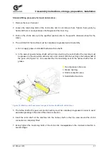
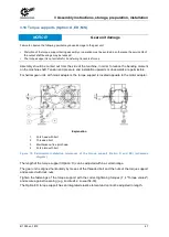
Explanation
1 Intake connection
2 Pump
3 Heat exchanger
4 Cooling system pressure connection
5 Temperature monitor (PT100)
6 Cooling water connection
Figure 18: Hydraulic plan of industrial gear units with CS1-X and CS2-X cooling systems
Pos: 84 /Allgemein/Allgemeing ültige M odul e/---------Seitenumbruch kompakt --------- @ 13\mod_1476369695906_0.docx @ 2265495 @ @ 1
Summary of Contents for B 1050 Series
Page 1: ...B 1050 en Industrial gear units Operating and Assembly Instructions...
Page 5: ...Publisher B 1050 en 1819 5...
Page 87: ...7 Appendix B 1050 en 1819 87 Gear units SK 5207 SK 10507 M3 oil screw holes...
Page 89: ...7 Appendix B 1050 en 1819 89 Gear units SK 5207 SK 10507 M5 oil screw holes...
Page 93: ...7 Appendix B 1050 en 1819 93 Gear units SK 11207 SK 15507 M3 oil screw holes...
Page 95: ...7 Appendix B 1050 en 1819 95 Gear units SK 11207 SK 15507 M5 oil screw holes...
Page 112: ...6052902 1819...