


IP390
, 105i & 105s
Security Platform Installation Guide
11
Figures
Figure 1 Component Locations Front View . . . . . . . . . . . . . . . . . 20
Figure 2 Component Locations Rear View . . . . . . . . . . . . . . . . . 21
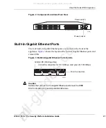
Figure 3 Built-In Gigabit Ethernet Ports Details . . . . . . . . . . . . . . 21
Figure 4 Appliance Status LEDs . . . . . . . . . . . . . . . . . . . . . . . . . 23
Figure 5 Location of the PCMCIA Card Slot . . . . . . . . . . . . . . . . 25
Figure 6 Mounting Screws Location . . . . . . . . . . . . . . . . . . . . . . 30
Figure 7 Adjustable Mounting Brackets . . . . . . . . . . . . . . . . . . . . 31
Figure 8 Back Panel Power Switch and Socket . . . . . . . . . . . . . 32
Figure 9 Nokia Network Voyager Reference Access Points . . . . 47
Figure 10 Four-Port Ethernet NIC Front Panel Details . . . . . . . . 62
Figure 11 Output Connector for the Ethernet Cable . . . . . . . . . . 64
Figure 12 Ethernet Crossover-Cable Pin Connections . . . . . . . . 64
Figure 13 Gigabit Ethernet Crossover Cable Pin Connections . . 65
Figure 14 Two-Port Copper Gigabit Ethernet NIC . . . . . . . . . . . . 66
Figure 15 Copper Gigabit Ethernet Cable Connector Output Pin
Assignments . . . . . . . . . . . . . . . . . . . . . . . . . . . . . . . . 67
Figure 16 Gigabit Ethernet Crossover Cable Pin Connections . . 67
Figure 17 Two-Port Fiber-Optic Gigabit Ethernet NIC . . . . . . . . . 69
Figure 18 Compact Flash Memory Card Slot . . . . . . . . . . . . . . . 73
Figure 19 Hard-Disk Drive Location . . . . . . . . . . . . . . . . . . . . . . 79
Figure 20 DIMM Socket Locations . . . . . . . . . . . . . . . . . . . . . . . 87
All manuals and user guides at all-guides.com
all-guides.co
m