General power checking troubleshooting
Troubleshooting flow
RM-88
BB Troubleshooting and Manual Tuning Guide
Nokia Customer Care
Issue 1
COMPANY CONFIDENTIAL
Page 6 –7
Copyright © 2006 Nokia. All rights reserved.
Page 1: ...Service Manual RM 88 Nokia E62 Mobile Terminal Part No 9250256 Issue 1 Nokia Customer Care COMPANY CONFIDENTIAL Copyright 2006 Nokia All rights reserved ...
Page 2: ...ce Tools and Service Concepts 5 Disassembly Reassembly Instructions 6 BB Troubleshooting and Manual Tuning Guide 7 RF Troubleshooting and Manual Tuning Guide 8 System Module 9 Schematics Glossary RM 88 Nokia E62 Service Manual Structure Nokia Customer Care Issue 1 COMPANY CONFIDENTIAL Page ix Copyright 2006 Nokia All rights reserved ...
Page 3: ...ailable for the product Do not attempt to discharge the battery by any other means Use the battery only for its intended purpose Never use any charger or battery which is damaged Do not short circuit the battery Accidental short circuiting can occur when a metallic object coin clip or pen causes direct connection of the and terminals of the battery metal strips on the battery for example when you ...
Page 4: ...MOBILE PHONES Business Group should be notified in writing e mail Please state Title of the Document Issue Number Date of publication Latest Amendment Number if applicable Page s and or Figure s in error Please send to NOKIA CORPORATION Nokia Mobile Phones Business Group Nokia Customer Care PO Box 86 FIN 24101 SALO Finland E mail Service Manuals nokia com RM 88 Company Policy Nokia Customer Care I...
Page 5: ...s and warp or melt certain plastics Do not store the phone in cold areas When it warms up to its normal temperature moisture can form inside which may damage electronic circuit boards Do not drop knock or shake the phone Rough handling can break internal circuit boards Do not use harsh chemicals cleaning solvents or strong detergents to clean the phone Do not paint the phone Paint can clog the mov...
Page 6: ...aged by static electricity discharge All ESD sensitive parts must be packed in metallized protective bags during shipping and handling outside any ESD Protected Area EPA Every repair action involving opening the product or handling the product components must be done under ESD protection ESD protected spare part packages MUST NOT be opened closed out of an ESD Protected Area For more information a...
Page 7: ...TIONS MAKE SURE YOU HAVE SWITCHED OFF ALL EQUIPMENT Cautions Servicing and alignment must be undertaken by qualified personnel only Ensure all work is carried out at an anti static workstation and that an anti static wrist strap is worn Ensure solder wire or foreign matter does not enter the telephone as damage may result Use only approved components as specified in the parts list Ensure all compo...
Page 8: ...circumstances shall Nokia be responsible for any loss of data or income or any special incidental consequential or indirect damages howsoever caused The contents of this document are provided as is Except as required by applicable law no warranties of any kind either express or implied including but not limited to the implied warranties of merchantability and fitness for a particular purpose are m...
Page 9: ...ndment Record Sheet Amendment No Date Inserted By Comments Issue 1 06 2006 ET RM 88 Nokia Customer Care Amendment Record Sheet Page ii COMPANY CONFIDENTIAL Issue 1 Copyright 2006 Nokia All rights reserved ...
Page 10: ...RM 88 Nokia Customer Care Nokia E62 Service Manual Structure This page left intentionally blank Page x COMPANY CONFIDENTIAL Issue 1 Copyright 2006 Nokia All rights reserved ...
Page 11: ...1 General Information Nokia Customer Care Issue 1 COMPANY CONFIDENTIAL Page 1 1 Copyright 2006 Nokia All rights reserved ...
Page 12: ...eriods only Intermittent operation 40oC 15oC 70oC 85 oC Operation not guaranteed but an attempt to operate does not damage the phone No operation or storage 40oC 85oC No storage or operation an attempt may damage the phone Charging allowed 25oC 50oC Long term storage conditions 0oC 85oC DC characteristics Signal Min Nom Max Note VBAT 3 1V 3 7V 4 2V charging high limit voltage 3 1V SW cut off RM 88...
Page 13: ...requency band GSM850 869 894 MHz EGSM900 925 960 MHz GSM1800 1805 1880 MHz GSM1900 1930 1990 MHz Tx frequency band GSM850 824 849 MHz EGSM900 880 915 MHz GSM1800 1710 1785 MHz GSM1900 1850 1910 MHz Output power GSM850 5 33 dBm 3 2mW 2W GSM900 5 31 2dBm 3 2mW 1 3 W GSM1800 0 30dBm 1 0mW 1W GSM1900 0 30 9dBm 1 0mW 1 26W Number of RF channels GSM850 123 GSM900 173 GSM1800 373 GSM1900 298 Channel spac...
Page 14: ...18 Mini SD card 512 MB MU 23 Mini SD card 1GB MU 24 Table 3 Power Enhancement Type Battery BP 5L Nokia Compact Charger AC 3U Nokia Travel Charger AC 4U Charger Adapter CA 44 Table 4 Messaging Enhancement Type Wireless Keyboard upgrade SU 8W Table 5 Positioning Enhancement Type Wireless GPS Module update LD 1W Table 6 Car Enhancement Type Wireless Plug in Car Handsfree HF 6W RM 88 General Informati...
Page 15: ...kage Transceiver RM 88 BP 5L Li ion Battery Cell AC 4U Charger User Guide CD ROM Headset HS 40 USB Cable DKE 2 Quick Start Guide Product and module list Module name Type code Notes System RF Module 1QR Main PWB with components EL Dome sheet Chassis Assy Display Module Keyboard A cover Assy SW Module Mobile enhancements Table 1 Audio Enhancement Type Mono Headset HS 40 Basic Stereo Headset HS 47 RM...
Page 16: ...lso MIDP Java 2 0 CLDC1 1 providing a good platform for 3rd party applications Figure 1 View of RM 88 RM 88 product features and sales package Bearers transport GSM Quadband World Phone E850 900 1800 1900 EGPRS class B Multislot class 11 Software platform SW platform Nokia Series 60 rel 3 0 Connectivity Bluetooth Headset Handsfree profiles BIP GOP Mini SD Card Mini USB interface PC Suite connectiv...
Page 17: ...RM 88 Nokia Customer Care General Information This page left intentionally blank Page 1 4 COMPANY CONFIDENTIAL Issue 1 Copyright 2006 Nokia All rights reserved ...
Page 18: ...8 Main RF characteristics for GSM850 900 1800 1900 phones 1 8 Battery endurance 1 9 Environmental conditions 1 9 List of Tables Table 1 Audio 1 6 Table 2 Data 1 7 Table 3 Power 1 7 Table 4 Messaging 1 7 Table 5 Positioning 1 7 Table 6 Car 1 7 List of Figures Figure 1 View of RM 88 1 5 RM 88 General Information Nokia Customer Care Issue 1 COMPANY CONFIDENTIAL Page 1 3 Copyright 2006 Nokia All right...
Page 19: ...RM 88 Nokia Customer Care General Information This page left intentionally blank Page 1 2 COMPANY CONFIDENTIAL Issue 1 Copyright 2006 Nokia All rights reserved ...
Page 20: ...RM 88 Nokia Customer Care General Information This page left intentionally blank Page 1 10 COMPANY CONFIDENTIAL Issue 1 Copyright 2006 Nokia All rights reserved ...
Page 21: ...2 Parts Lists and Component Layouts Nokia Customer Care Issue 1 COMPANY CONFIDENTIAL Page 2 1 Copyright 2006 Nokia All rights reserved ...
Page 22: ...RM 88 Nokia Customer Care Parts Lists and Component Layouts This page left intentionally blank Page 2 2 COMPANY CONFIDENTIAL Issue 1 Copyright 2006 Nokia All rights reserved ...
Page 23: ...2 7 Component layouts 2 30 Components overview 2 30 Component layout bottom 1qr_10a_asmdrw_b 2 31 Component layout top 1qr_10a_asmdrw_t 2 32 List of Figures Figure 2 Exploded view of RM 88 2 5 RM 88 Parts Lists and Component Layouts Nokia Customer Care Issue 1 COMPANY CONFIDENTIAL Page 2 3 Copyright 2006 Nokia All rights reserved ...
Page 24: ...RM 88 Nokia Customer Care Parts Lists and Component Layouts This page left intentionally blank Page 2 4 COMPANY CONFIDENTIAL Issue 1 Copyright 2006 Nokia All rights reserved ...
Page 25: ...Exploded view Exploded view Figure 2 Exploded view of RM 88 RM 88 Parts Lists and Component Layouts Nokia Customer Care Issue 1 COMPANY CONFIDENTIAL Page 2 5 Copyright 2006 Nokia All rights reserved ...
Page 26: ...MD12402 TORX SILV 6 I008 SCREW M1 4X3 4 TORX PLUS 4IP 1 I007 Remform screw 1 8x8 1 I019 Battery Release Spring 1 I028 BLANK LABEL 29mmx18mm EXP65673 1 I021 Joystick Button 040 012658 1 I018 Battery Release Button 040 012946 1 I023 Joystick module tape 040 020164 1 I005 XXXXXXX Operator Logo painted Silver 040 012438 1 I027 XXXXXXX Antenna Lid painted Silver 040 012654 1 I029 Battery Cover painted ...
Page 27: ...LD_PWB _CAN_RAP SHIELD PWB CAN RAP A4801 Bottom K 10 SHIELD_040 _017960 PWB CAN COMBO A4802 Bottom L 7 SHIELD_PWB _CAN_APE SHIELD PWB CAN APE A6001 Bottom L 4 SHIELD_PWB _CAN_WCDM A SHIELD PWB CAN WCDMA A7506 Bottom G 16 SHIELD_PWB _CAN_PA SHIELD PWB CAN Pa A7507 Bottom G 13 SHIELD_PWB _CAN_PIHI SHIELD PWB CAN PIHI B2200 Bottom C 10 CRYSTAL_3 3 X1 6_H0 9 CRYSTAL 32 768KHZ 30PPM 12 5PF 32 768kHz C2...
Page 28: ...02C Chipcap 5 NP0 47p 50V C2071 Bottom K 18 TANT_C_6 2 X3 4_H1 7 CHIPTCAP 150U M 10V 6X3 2X1 5 150u_10V 10V C2100 Bottom G 3 0402C CHIPCAP X7R 33N K 10V 0402 33n 10V C2101 Bottom G 3 0402C CHIPCAP X7R 33N K 10V 0402 33n 10V C2102 Bottom G 3 0603C CHIPCAP X5R 2U2 K 6V3 0603 2u2 6V3 C2103 Top F 22 0402C Chipcap 5 X7R 1n0 50V C2104 Top F 22 0402C Chipcap 5 X7R 1n0 50V C2200 Bottom B 9 0603C CHIPCAP X...
Page 29: ...m C 7 0402C CHIPCAP X5R 1U5 K 4V 0402 1u5 4V C2213 Bottom D 9 0402C CHIPCAP X5R 1U5 K 4V 0402 1u5 4V C2214 Bottom D 9 0402C CHIPCAP X5R 1U5 K 4V 0402 1u5 4V C2215 Bottom E 8 0402C CHIPCAP X5R 1U5 K 4V 0402 1u5 4V C2216 Bottom E 8 0402C CHIPCAP X5R 1U5 K 4V 0402 1u5 4V C2217 Bottom D 10 0402C CHIPCAP X5R 1U5 K 4V 0402 1u5 4V C2218 Bottom C 9 0402C Chipcap X7R 10 50V 0402 1n0 50V C2219 Bottom D 10 0...
Page 30: ...PCAP X5R 10U M 6V3 0805 10U 6V3 C2232 Bottom D 8 0603C CHIPCAP X5R 1U K 6V3 0603 1u0 6 3V C2270 Bottom B 8 0402C Chipcap X7R 10 50V 0402 1n0 50V C2271 Bottom B 8 0402C Chipcap X7R 10 50V 0402 1n0 50V C2272 Bottom B 9 0402C Chipcap X7R 10 50V 0402 1n0 50V C2273 Bottom C 7 0402C Chipcap X7R 10 50V 0402 1n0 50V C2274 Bottom C 7 0402C Chipcap X7R 10 50V 0402 1n0 50V C2275 Bottom B 7 0402C Chipcap X7R ...
Page 31: ... 5 0603C CHIPCAP X5R 1U K 6V3 0603 1u0 6 3V C2314 Bottom D 6 0603C CHIPCAP X5R 4U7 K 6V3 0603 4u7 6 3V C2315 Bottom E 7 0603C_H0 9 5 CHIPCAP X5R 1U K 25V 0603 1u0 25V C2316 Bottom E 7 0402C Chipcap 5 NP0 56p 50V C2317 Bottom D 7 0402C Chipcap 5 NP0 27p 50V C2319 Bottom E 7 0603C_H0 9 5 CHIPCAP X5R 1U K 25V 0603 1u0 25V C2700 Bottom D 16 0402C_H0 6 CHIPCAP X5R 100N M 16V 0402 100n 16V C2800 Bottom ...
Page 32: ...16V 0402 100n 16V C2811 Bottom L 9 0402C_H0 6 CHIPCAP X5R 100N M 16V 0402 100n 16V C2812 Bottom I 10 0402C_H0 6 CHIPCAP X5R 100N M 16V 0402 100n 16V C2813 Bottom L 12 0402C_H0 6 CHIPCAP X5R 100N M 16V 0402 100n 16V C2814 Bottom I 11 0402C_H0 6 CHIPCAP X5R 100N M 16V 0402 100n 16V C2815 Bottom K 12 0402C_H0 6 CHIPCAP X5R 100N M 16V 0402 100n 16V C2818 Bottom J 12 0402C_H0 6 CHIPCAP X5R 100N M 16V 0...
Page 33: ...om L 8 0402C_H0 6 CHIPCAP X5R 100N M 16V 0402 100n 16V C3007 Bottom M 6 0402C Chipcap X7R 10 16V 0402 10n 16V C3008 Bottom J 7 0402C_H0 6 CHIPCAP X5R 100N M 16V 0402 100n 16V C3009 Bottom M 7 0402C_H0 6 CHIPCAP X5R 100N M 16V 0402 100n 16V C3010 Bottom J 12 0402C Chipcap 0 25pF NP0 3p3 50V C3011 Bottom J 6 0402C_H0 6 CHIPCAP X5R 100N M 16V 0402 100n 16V C3017 Bottom L 8 0402C_H0 6 CHIPCAP X5R 100N...
Page 34: ..._H0 6 CHIPCAP X5R 100N M 16V 0402 100n 16V C4411 Bottom I 2 0402C Chipcap 5 NP0 27p 50V C4414 Bottom I 5 0603C CHIPCAP X5R 1U K 16V 0603 1u0 16V C4420 Bottom B 13 0402C Chipcap X7R 5 16V 0402 10n 16V C4421 Bottom B 13 0402C Chipcap X7R 5 16V 0402 10n 16V C4424 Bottom I 5 0402C CHIPCAP X5R 1U K 6V3 0402 1u0 6 3V C5200 Bottom L 12 0402C_H0 6 CHIPCAP X5R 100N M 16V 0402 100n 16V C5201 Bottom M 11 060...
Page 35: ...6V C6039 Bottom J 4 0402C Chipcap 5 NP0 18p 50V C6041 Bottom K 3 0402C Chipcap 0 25pF NP0 2p7 50V C6042 Bottom K 4 0402C Chipcap 0 25pF NP0 2p7 50V C6050 Bottom K 3 0402C CHIPCAP X5R 1U K 6V3 0402 1u0 6 3V C7501 Bottom H 13 0402C Chipcap 0 25pF NP0 2p7 50V C7503 Bottom F 12 0603C CHIPCAP X5R 1U K 6V3 0603 1u0 6 3V C7504 Bottom H 13 0603C CHIPCAP X5R 1U K 6V3 0603 1u0 6 3V C7505 Bottom F 12 0402C C...
Page 36: ... 0402 100n 10V C7520 Bottom H 16 0402C Chipcap 0 25pF NP0 3p3 50V C7522 Bottom F 16 0402C Chipcap 0 25pF NP0 1p8 50V C7523 Bottom H 16 0402C CHIPCAP X5R 1U K 6V3 0402 1u0 6 3V C7524 Bottom F 15 0402C CHIPCAP X5R 1U K 6V3 0402 1u0 6 3V C7525 Bottom F 17 0402C Chipcap 5 NP0 18p 50V C7530 Bottom M 4 0402C Chipcap X7R 10 25V 0402 4n7 25V C7590 Bottom L 3 0402C Chipcap X7R 5 16V 0402 10n 16V C7591 Top ...
Page 37: ...C EP RTC BACUP CAPAC 311 SIZE FOR 2 6V 4UAH 2 6V G7500 Bottom H 12 VCO_DCS027 33 VCO 3296 3980MH Z 4 BAND MATSUSHITA 3296 3980 MHz G7501 Bottom F 11 NKG3176B_ H1 0 VCTCXO 38 4MHZ 2 5V 38 4MHz L2000 Bottom D 4 0603_BLM FERR BEAD 220R 100M 2A 0R05 0603 220R 100MHz L2100 Top F 23 0405_2_MAT SU CHIP BEAD ARRAY 2X1000R 0405 2x1000R 100MHz L2102 Bottom B 20 COIL_0603C S CHIP COIL 56N J Q38 250MHZ 0603 5...
Page 38: ... 0R05 0603 220R 100MHz L2273 Bottom B 8 0603_BLM FERR BEAD 220R 100M 2A 0R05 0603 220R 100MHz L2301 Bottom B 5 0603_BLM FERR BEAD 220R 100M 2A 0R05 0603 220R 100MHz L2302 Bottom B 6 CHOKE_SER4 00_H1 2 INDUCT WW 10UH 0A65 0R35 4X4X1 2 10uH L2304 Bottom D 6 CHOKE_SER3 00 CHOKE 22U M 1R5 0 35A 22uH L2305 Bottom D 5 FERRITE_04 02 FERRITE BEAD 0 6R 600R 100MHZ 0402 600R 100MHz L2306 Bottom C 5 FERRITE_...
Page 39: ...J Q29 800M 0402 18nH L7501 Bottom G 14 0402L CHIP COIL 33N J Q23 800M 0402 33nH L7502 Bottom F 13 FERRITE_04 02 FERRITE BEAD 0 6R 600R 100MHZ 0402 600R 100MHz L7503 Bottom F 16 0402LQW CHIP COIL 27N C Q25 250MHZ 0402 27nH L7504 Bottom G 14 0402L CHIP COIL 47N J Q23 800M 0402 47nH L7505 Bottom G 14 0402L CHIP COIL 22N J Q28 800M 0402 22nH L7515 Bottom H 12 0402L_H0 4 5 CHIP COIL 4N7 0N1 Q29 1GHZ 04...
Page 40: ...MW 8BUMP USMD8 N4401 Bottom H 2 IRDA_RPM9 60 IRDA 1 15MBPS 2 2MM ROHS N4402 Bottom H 4 MSOP_10 EL DRIVER D381B 2 7V MSOP 10 N4403 Bottom E 13 SC70_5 1XOP AMP 2 7 5 5V LMV321 SC70 5 N5200 Bottom M 11 USMD16_2 0 3X2 03 VREG LEVEL SHIFT LP3928 USMD16 2 8V N6030 Bottom L 4 CSP_47_3 85 X4 05 BC4 ROM1 0RDL N7505 Bottom G 13 TFBGA144 AHNE301A TRANCEIVER RFIC TFBGA144 N7520 Bottom G 16 RF9282E3 6 PA RF928...
Page 41: ...120K J 0404 220k 120k R2015 Bottom D 4 BGA4_1 01X 1 07 ASIP TVS BGA4 R2025 Bottom F 4 0402R Resistor 5 63mW 10R R2026 Bottom F 4 0402R Resistor 5 63mW 10R R2030 Bottom I 3 0402R Resistor 5 63mW 100R R2070 Bottom K 18 0402_VAR CHIP VARISTOR VWM14V VC50V 0402 14V 50V R2071 Bottom C 10 0402_NTH5 NTC RES 47K J B 4050 3 0402 47k R2100 Bottom G 3 FLIP_CHIP_8 _1 7X1 7 ASIP SINGLE ENDED MICROPHONE INTERF ...
Page 42: ...tom B 9 0402R Resistor 5 63mW 1k0 R2207 Bottom B 10 0402R Resistor 5 63mW 1k0 R2208 Bottom B 10 0402R Resistor 5 63mW 1k0 R2209 Bottom B 10 0402R Resistor 5 63mW 1k0 R2212 Bottom B 9 0402R Resistor 5 63mW 470R R2213 Bottom D 10 0402R Resistor 5 63mW 4k7 R2214 Bottom E 10 0402R Resistor 5 63mW 4k7 R2216 Bottom D 10 0402R CHIPRES 0W06 2M2 J 0402 2M2 R2307 Bottom C 5 0402R Resistor 5 63mW 100R R2310 ...
Page 43: ...k R4403 Top A 22 0402_NTH5 NTC RES 47K J B 4050 3 0402 47k R4404 Bottom I 5 0402R Chipres 0W06 jumper 0402 0R R4406 Top L 22 0402_VAR CHIP VARISTOR VWM14V VC50V 0402 14V 50V R4407 Bottom D 13 0402R Resistor 5 63mW 18R R4409 Bottom D 13 0402R Resistor 5 63mW 18R R4410 Bottom D 14 0402R Resistor 5 63mW 1k0 R4412 Top B 22 0402R Resistor 5 63mW 680R R4413 Top C 22 0402R Chipres 0W06 jumper 0402 0R R44...
Page 44: ...mper 0402 0R R4508 Bottom B 17 0402R Chipres 0W06 jumper 0402 0R R4509 Bottom B 16 0402R Chipres 0W06 jumper 0402 0R R5201 Bottom M 10 0402R Resistor 5 63mW 100k R5202 Bottom L 10 0402R Resistor 5 63mW 100k R5203 Bottom M 11 0402R Resistor 5 63mW 100k R5204 Bottom L 11 0402R Resistor 5 63mW 2k2 R6030 Bottom L 3 0402R Resistor 5 63mW 10k R6031 Bottom K 4 0402R Resistor 5 63mW 10k R6032 Bottom L 4 0...
Page 45: ...5 63mW 10R R7509 Bottom F 12 0402R Resistor 5 63mW 22k R7510 Bottom F 17 0402R Resistor 5 63mW 15R R7522 Bottom F 16 0402R CHIPRES 0W06 27K F 0402 27k R7523 Bottom H 16 0402R Chipres 0W06 jumper 0402 0R R7586 Bottom L 4 0402R Resistor 5 63mW 330R R7587 Bottom M 3 0402R Chipres 0W06 jumper 0402 0R R7588 Top J 23 0402R Chipres 0W06 jumper 0402 0R R7590 Bottom M 4 0402R Resistor 5 63mW 1k8 R7591 Top ...
Page 46: ..._76 DI ZEN 100V 6 200MW SOD323 V4402 Bottom J 4 SC_76 DI ZEN 100V 6 200MW SOD323 V4403 Bottom E 14 VMT3 TR 2SC5658QRS N 50V 0A1 0W15 VMT3 V4404 Bottom H 4 SOT_666 TRX2 RX4 PEMD9 N P 10K 47K 0W12 SOT666 V4405 Top B 22 LED_CL191 LED CL 191WB D T WHITE 0 115MCD 0603 V4406 Top B 22 EM3 TR PDTC114EE N 50V RB RBE 10K EM3 V4407 Bottom B 14 EM3 TR PDTC114EE N 50V RB RBE 10K EM3 V7590 Bottom M 3 SOT323 Tr ...
Page 47: ...m D 20 CONN_ANT_ DMD11562 CON PPP ANTENNA R1024 DMD11562 X2701 Bottom C 15 SIM_CONN_ M_SK_20030 0383 SM SIM CONN 2X3POL P2 54 H4 6 X4400 Top E 22 JST_R_JAVK_ G_1_R3 SM CONN 2X12F P0 4 30V 3A PWB PWB X4500 Bottom F 8 CONN_SD_54 742_002 SM LCD CONN 1X8 P2 0 SPR 50V 0 5A X4501 Bottom B 17 SMK_4309_B _B_6P_V2 SM CONN 6P SPR P1 3 50V BTOB X5200 Bottom K 15 MINISD_SC1 S011V1S3 CONN MINISD PUSH PUSH 3 3V...
Page 48: ... 6R 600R 100MHZ 0402 600R 100MHz Z4402 Top B 23 uBGA25_2 4 7X2 47 ASIP 10 CH ESD EMI FILTER BGA25 Z4403 Top C 23 uBGA25_2 4 7X2 47 ASIP 10 CH ESD EMI FILTER BGA25 Z4500 Bottom B 13 uBGA24_2 6 2X2 62 ASIP EMIF10 1K010 F2 PB FREE Z4501 Bottom D 12 uBGA24_2 6 2X2 62 ASIP EMIF10 1K010 F2 PB FREE Z5200 Bottom M 12 uBGA11_1 6 2X2 12 ASIP EMIF04 MMC02F2 PB FREE Z6030 Bottom K 4 EZFVQ42NM 61S LTCC FILT 24...
Page 49: ... 850 900MH z Z7504 Bottom G 15 FILTER_2 1X 1 7_10P_H0 65 DUAL RX SAW FILTER 850 900MHZ 2016 850 900MH z Z7520 Bottom H 16 FERRITE_FB MJ1608 FERRITE BEAD 0R01 28R 100MHZ 0603 28R 100MHz RM 88 Parts Lists and Component Layouts Nokia Customer Care Issue 1 COMPANY CONFIDENTIAL Page 2 29 Copyright 2006 Nokia All rights reserved ...
Page 50: ...Component layouts Components overview RM 88 Nokia Customer Care Parts Lists and Component Layouts Page 2 30 COMPANY CONFIDENTIAL Issue 1 Copyright 2006 Nokia All rights reserved ...
Page 51: ...Component layout bottom 1qr_10a_asmdrw_b RM 88 Parts Lists and Component Layouts Nokia Customer Care Issue 1 COMPANY CONFIDENTIAL Page 2 31 Copyright 2006 Nokia All rights reserved ...
Page 52: ...Component layout top 1qr_10a_asmdrw_t RM 88 Nokia Customer Care Parts Lists and Component Layouts Page 2 32 COMPANY CONFIDENTIAL Issue 1 Copyright 2006 Nokia All rights reserved ...
Page 53: ...3 Service Software Instructions Nokia Customer Care Issue 1 COMPANY CONFIDENTIAL Page 3 1 Copyright 2006 Nokia All rights reserved ...
Page 54: ...RM 88 Nokia Customer Care Service Software Instructions This page left intentionally blank Page 3 2 COMPANY CONFIDENTIAL Issue 1 Copyright 2006 Nokia All rights reserved ...
Page 55: ...Figure 10 Data package setup information 3 13 Figure 11 Data package destination folder 3 14 Figure 12 InstallShield Wizard Complete 3 15 Figure 13 Uninstalling phone data package 3 16 Figure 14 Finishing data package uninstallation 3 16 Figure 15 Phoenix login 3 17 Figure 16 New user configured 3 17 Figure 17 Select mode Manual 3 18 Figure 18 Connections list 3 19 Figure 19 Connection information...
Page 56: ...RM 88 Nokia Customer Care Service Software Instructions This page left intentionally blank Page 3 4 COMPANY CONFIDENTIAL Issue 1 Copyright 2006 Nokia All rights reserved ...
Page 57: ...have been installed The phone model specific data package includes all changing product specific data Product software binary files Files for type label printing Validation file for the faultlog repair data reporting system All product specific configuration files for Phoenix software components Note Phoenix and phone data packages should only be used as complete installation packages Uninstallati...
Page 58: ...ing the installation procedure you may get the following message Figure 3 Dongle not found This may be a result of a defective or too old PKD 1 dongle Check the COM parallel ports used After correcting the problem you can restart the installation For more detailed information please refer to Phoenix Help files Tip Each feature in Phoenix has its own Help function which can be activated while runni...
Page 59: ...d and updated The process may take several minutes to complete If the operating system does not require rebooting the PC components are registered right away If the operating system requires restarting your computer the Install Shield Wizard will notifies about it Select Yes to reboot the PC immediately or No to reboot the PC manually afterwards After the reboot all components are registered Note ...
Page 60: ... automatically without uninstallation Always use the latest available versions of both Phoenix and the phone specific data package Instructions can be found in the phone model specific Technical Bulletins and phone data package readme txt files shown during installation If you try to update Phoenix with the same version you already have for example a15_2004_24_7_55 to a15_2004_24_7_55 you are aske...
Page 61: ...ice_sw_2004_39_x_xx exe Results A new Phoenix version is installed and driver versions are checked and updated Uninstalling Phoenix Context You can uninstall Phoenix service software manually from the Windows Control Panel Steps 1 Open the Windows Control Panel and choose Add Remove Programs RM 88 Service Software Instructions Nokia Customer Care Issue 1 COMPANY CONFIDENTIAL Page 3 9 Copyright 200...
Page 62: ...rogram The progress of the uninstallation is shown 3 If the operating system does not require rebooting click Finish to complete Figure 8 Finish uninstallation RM 88 Nokia Customer Care Service Software Instructions Page 3 10 COMPANY CONFIDENTIAL Issue 1 Copyright 2006 Nokia All rights reserved ...
Page 63: ...n Windows Control Panel Add Remove Programs 2 Choose Phoenix Service Software Change Remove 3 In the following view select Repair Figure 9 Repair program Phoenix reinstalls components and registers them The procedure is the same as when updating Phoenix 4 To complete the repair click Finish Phone data package overview Each product has its own data package DP The product data package contains all p...
Page 64: ...omputer for example in C TEMP Close all other programs XX XX type designator of the product If you already have Phoenix installed on your computer you will need to update it when a new version is released Note Often Phoenix and the phone specific data package come in pairs meaning that a certain version of Phoenix can only be used with a certain version of a data package Always use the latest avai...
Page 65: ...ext carefully There is information about the Phoenix version required with this data package Figure 10 Data package setup information 4 To continue click Next RM 88 Service Software Instructions Nokia Customer Care Issue 1 COMPANY CONFIDENTIAL Page 3 13 Copyright 2006 Nokia All rights reserved ...
Page 66: ...e destination folder The InstallShield Wizard checks where Phoenix is installed and the directory is shown 6 To start copying the files click Next RM 88 Nokia Customer Care Service Software Instructions Page 3 14 COMPANY CONFIDENTIAL Issue 1 Copyright 2006 Nokia All rights reserved ...
Page 67: ...ge Context There is no need to uninstall an older version of a data package unless instructions to do so are given in the readme txt file of the data package and bulletins related to the release Please read all related documents carefully Steps 1 Locate the data package installation file e g XX XX_dp_EA_v_1_0 exe from your computer 2 To start the uninstallation procedure double click the data pack...
Page 68: ...stalled click Finish Figure 14 Finishing data package uninstallation Alternative steps You can also uninstall the data package manually from Control Panel Add Remove Programs xx xx Phone Data Package type designator of the phone RM 88 Nokia Customer Care Service Software Instructions Page 3 16 COMPANY CONFIDENTIAL Issue 1 Copyright 2006 Nokia All rights reserved ...
Page 69: ...ctions in Phoenix Context With the Manage Connections feature you can edit and delete existing connections or create new ones Note After choosing the desired connection and connecting the phone to a PC for the first time allow the PC to install the USB device drivers first Please note that this may take some time to complete If there are problems after the driver installation check that the USB co...
Page 70: ...on choose the following connection settings Media FPS 10 TCP IP NET_SERV_NAME Click Scan Choose your own FPS 10 device based on the correct MAC address See Serial No from the label attached to the bottom of your FPS 10 PORT_NUM Use the default value and click Next PROTOCOL_FAMILY Use the default value and click Next SOCKET TYPE Use the default value and click Next TX_BUFFER_SIZE Use the default va...
Page 71: ...e from RM 1 Installing flash support files for FPS 10 Prerequisites Note You need to install flash support files for FPS 10 only if you don t have the latest Phoenix available or the flash support files have changed after the latest Phoenix release Flash support files are installed automatically when you install Phoenix Use Phoenix packages later than June 2006 Normally it is enough to install Pho...
Page 72: ...ou try to downgrade the existing version to older ones the setup will be aborted If you really want to downgrade uninstall newer files manually from Control Panel and then rerun the installation again Figure 22 Flash installation interrupted If an older version exists on your PC and it needs to be updated click Next to continue installation RM 88 Nokia Customer Care Service Software Instructions P...
Page 73: ...to continue Figure 23 Flash destination folder When installing the flash update files for the first time you may choose another location by selecting Browse However this is not recommended RM 88 Service Software Instructions Nokia Customer Care Issue 1 COMPANY CONFIDENTIAL Page 3 21 Copyright 2006 Nokia All rights reserved ...
Page 74: ... Choose Flashing Prommer maintenance 3 When the new flash update package is installed to the computer you will be asked to update the files to your Prommer To update the files click Yes Click OK if the computer informs you about an unsafe removal of the device 4 Alternatively you can update the FPS 10 flash prommer software by clicking the Update button RM 88 Nokia Customer Care Service Software I...
Page 75: ...heck also the status leds in the FPS 10 The MODE2 led green VBAT and POWER leds red should be lit If you are using LAN connection the LAN led yellow should be blinking 7 Check that your FPS 10 flash prommer has enough memory Flashing the RM 88 with FPS 10 needs at least 128 MB of SRAM memory in the prommer Figure 26 Prommer maintenance window RM 88 Service Software Instructions Nokia Customer Care...
Page 76: ...7 Flash directory window All files can be loaded separately to the prommer used To do this click the right mouse button in the Flash box files window and select the file type to be loaded More information can be found in Phoenix Help RM 88 Nokia Customer Care Service Software Instructions Page 3 24 COMPANY CONFIDENTIAL Issue 1 Copyright 2006 Nokia All rights reserved ...
Page 77: ...4 Service Tools and Service Concepts Nokia Customer Care Issue 1 COMPANY CONFIDENTIAL Page 4 1 Copyright 2006 Nokia All rights reserved ...
Page 78: ...RM 88 Nokia Customer Care Service Tools and Service Concepts This page left intentionally blank Page 4 2 COMPANY CONFIDENTIAL Issue 1 Copyright 2006 Nokia All rights reserved ...
Page 79: ...15 RF testing and BB testing tuning 4 16 List of Tables Table 7 Attenuation table for MJ 67 4 8 Table 8 Attenuation table for antenna coupler SA 82 4 9 List of Figures Figure 28 Basic flash concept with FPS 10 4 11 Figure 29 MJ 67 module jig service concept 4 12 Figure 30 POS flash concept 4 13 Figure 31 Service concept for RF testing and RF BB tuning 4 14 Figure 32 CU 4 flash concept with FPS 10 ...
Page 80: ...RM 88 Nokia Customer Care Service Tools and Service Concepts This page left intentionally blank Page 4 4 COMPANY CONFIDENTIAL Issue 1 Copyright 2006 Nokia All rights reserved ...
Page 81: ...r supply Universal power supply CA 31D USB cable The CA 31D USB cable is used to connect FPS 10 or FPS 11 to a PC It is included in the FPS 10 and FPS 11 sales packages CA 56RS RF cable Small RF cable that is used for RF tuning with MJ 67 module jig RM 88 Service Tools and Service Concepts Nokia Customer Care Issue 1 COMPANY CONFIDENTIAL Page 4 5 Copyright 2006 Nokia All rights reserved ...
Page 82: ... FBUS and USB connections supported When using CU 4 note the special order of connecting cables and other service equipment Instructions 1 Connect a service tool jig flash adapter to CU 4 2 Connect CU 4 to your PC with a USB cable 3 Connect supply voltage 12 V 4 Connect an FBUS cable if necessary 5 Start Phoenix service software Note Phoenix enables CU 4 regulators via USB when it is started Recon...
Page 83: ...h prommer features Flash functionality for BB5 and DCT 4 terminals Smart Card reader for SX 2 or SX 4 USB traffic forwarding USB to FBUS Flashbus conversion LAN to FBUS Flashbus and USB conversion Vusb output switchable by PC command FPS 10 sales package includes FPS 10 prommer Power Supply with 5 country specific cords USB cable RM 88 Service Tools and Service Concepts Nokia Customer Care Issue 1...
Page 84: ...75 0 1 38 0 1 124 0 2 GSM 1800 512 0 3 698 0 2 885 0 1 GSM 1900 512 0 5 700 0 6 810 0 8 Measured with Universal Radio Communication Tester CMU 200 Note Tx attenuation tolerance is 0 5dB Rx attenuation tolerance is 1 0 dB RJ 86 Soldering jig RM 88 RM 89 specific soldering jig RM 88 Nokia Customer Care Service Tools and Service Concepts Page 4 8 COMPANY CONFIDENTIAL Issue 1 Copyright 2006 Nokia All ...
Page 85: ...tem Channel Tx att dB Rx att dB GSM 850 128 5 8 4 190 5 3 3 251 5 3 3 GSM 900 975 5 8 4 38 5 4 124 5 4 GSM 1800 512 7 7 6 698 7 4 6 885 7 2 5 GSM 1900 512 7 9 6 700 6 2 6 810 5 6 6 Note Tx attenuation tolerance is 0 5 dB Rx attenuation tolerance is 1 0dB SRT 6 Opening tool SRT 6 is used to open phone covers and B to B connectors RM 88 Service Tools and Service Concepts Nokia Customer Care Issue 1 ...
Page 86: ...SS 62 equipped with a clip interlock system provides standardised interface towards Control Unit provides RF connection using galvanic connector or coupler multiplexing between USB and FBUS media controlled by VUSB SS 76 Domesheet assembly jig RM 88 Nokia Customer Care Service Tools and Service Concepts Page 4 10 COMPANY CONFIDENTIAL Issue 1 Copyright 2006 Nokia All rights reserved ...
Page 87: ...5 Flash adapter SS 46 Interface adapter CA 35S Power cable XCS 4 Modular cable Standard USB cable FPS 10 Flash prommer box Standard USB cable PKD 1 SW security device RM 88 Service Tools and Service Concepts Nokia Customer Care Issue 1 COMPANY CONFIDENTIAL Page 4 11 Copyright 2006 Nokia All rights reserved ...
Page 88: ... Flash prommer box SX 4 Smart card XCS 4 Modular cable PCS 1 DC power cable Standard USB cable Standard USB cable GPIB control cable XRS 6 RF cable PKD 1 SW security device RF shield box RM 88 Nokia Customer Care Service Tools and Service Concepts Page 4 12 COMPANY CONFIDENTIAL Issue 1 Copyright 2006 Nokia All rights reserved ...
Page 89: ...S flash concept Type Description CA 53 USB connectivity cable FLS 5 POS flash device ACP 8 Power adapter RM 88 Service Tools and Service Concepts Nokia Customer Care Issue 1 COMPANY CONFIDENTIAL Page 4 13 Copyright 2006 Nokia All rights reserved ...
Page 90: ...dule jig CU 4 Control unit Standard USB cable PCS 1 DC power cable Standard USB cable smart card reader SX 4 Smart card XRS 6 RF cable GPIB control cable PKD 1 SW security device RF shield box RM 88 Nokia Customer Care Service Tools and Service Concepts Page 4 14 COMPANY CONFIDENTIAL Issue 1 Copyright 2006 Nokia All rights reserved ...
Page 91: ...scription Type SS 62 FS 5 Flash adapter CU 4 Control unit XCS 4 Modular cable PCS 1 Power cable FPS 10 Flash prommer box Standard USB cable Standard USB cable PKD 1 SW security device RM 88 Service Tools and Service Concepts Nokia Customer Care Issue 1 COMPANY CONFIDENTIAL Page 4 15 Copyright 2006 Nokia All rights reserved ...
Page 92: ...it SA 82 RF coupler PCS 1 Power cable XCS 4 Modular cable Standard USB cable Standard USB cable smart card reader SX 4 Smart card GPIB control cable XRS 6 RF cable PKD 1 SW security device RF shield box RM 88 Nokia Customer Care Service Tools and Service Concepts Page 4 16 COMPANY CONFIDENTIAL Issue 1 Copyright 2006 Nokia All rights reserved ...
Page 93: ...5 Disassembly Reassembly Instructions Nokia Customer Care Issue 1 COMPANY CONFIDENTIAL Page 5 1 Copyright 2006 Nokia All rights reserved ...
Page 94: ...RM 88 Nokia Customer Care Disassembly Reassembly Instructions This page left intentionally blank Page 5 2 COMPANY CONFIDENTIAL Issue 1 Copyright 2006 Nokia All rights reserved ...
Page 95: ...e of Contents Disassembly instructions 5 5 Tips for assembly 5 10 RM 88 Disassembly Reassembly Instructions Nokia Customer Care Issue 1 COMPANY CONFIDENTIAL Page 5 3 Copyright 2006 Nokia All rights reserved ...
Page 96: ...RM 88 Nokia Customer Care Disassembly Reassembly Instructions This page left intentionally blank Page 5 4 COMPANY CONFIDENTIAL Issue 1 Copyright 2006 Nokia All rights reserved ...
Page 97: ...Disassembly instructions RM 88 Disassembly Reassembly Instructions Nokia Customer Care Issue 1 COMPANY CONFIDENTIAL Page 5 5 Copyright 2006 Nokia All rights reserved ...
Page 98: ...RM 88 Nokia Customer Care Disassembly Reassembly Instructions Page 5 6 COMPANY CONFIDENTIAL Issue 1 Copyright 2006 Nokia All rights reserved ...
Page 99: ...RM 88 Disassembly Reassembly Instructions Nokia Customer Care Issue 1 COMPANY CONFIDENTIAL Page 5 7 Copyright 2006 Nokia All rights reserved ...
Page 100: ...RM 88 Nokia Customer Care Disassembly Reassembly Instructions Page 5 8 COMPANY CONFIDENTIAL Issue 1 Copyright 2006 Nokia All rights reserved ...
Page 101: ...RM 88 Disassembly Reassembly Instructions Nokia Customer Care Issue 1 COMPANY CONFIDENTIAL Page 5 9 Copyright 2006 Nokia All rights reserved ...
Page 102: ...Tips for assembly RM 88 Nokia Customer Care Disassembly Reassembly Instructions Page 5 10 COMPANY CONFIDENTIAL Issue 1 Copyright 2006 Nokia All rights reserved ...
Page 103: ...6 BB Troubleshooting and Manual Tuning Guide Nokia Customer Care Issue 1 COMPANY CONFIDENTIAL Page 6 1 Copyright 2006 Nokia All rights reserved ...
Page 104: ...RM 88 Nokia Customer Care BB Troubleshooting and Manual Tuning Guide This page left intentionally blank Page 6 2 COMPANY CONFIDENTIAL Issue 1 Copyright 2006 Nokia All rights reserved ...
Page 105: ...Bluetooth self tests in Phoenix 6 30 Bluetooth BER failure troubleshooting 6 32 BT audio failure troubleshooting 6 33 Audio troubleshooting 6 34 Audio troubleshooting test instructions 6 34 Internal earpiece troubleshooting 6 37 Internal microphone troubleshooting 6 38 IHF troubleshooting 6 39 External microphone troubleshooting 6 40 External earpiece troubleshooting 6 41 Introduction to acoustics...
Page 106: ...urement when earpiece is connected 6 35 Figure 40 Differential output waveform of the Ext_in_IHF_out out loop measurement when speaker is connected 6 35 Figure 41 Single ended output waveform of the HP_in_Ext_out loop when microphone is connected 6 36 RM 88 Nokia Customer Care BB Troubleshooting and Manual Tuning Guide Page 6 4 COMPANY CONFIDENTIAL Issue 1 Copyright 2006 Nokia All rights reserved ...
Page 107: ...med during startup Abnormal current consumption Flashing does not work Charging does not work Display does not work Keypad does not work Display backlight does not work Keyboard EL dome sheet does light up Mail indicator LED does not work Phone gives SIM card error Phone cannot access SD card USB does not work Audio earpiece microphone and or IHF does not work Audio headset does not work Volume ke...
Page 108: ...Baseband main troubleshooting Troubleshooting flow RM 88 Nokia Customer Care BB Troubleshooting and Manual Tuning Guide Page 6 6 COMPANY CONFIDENTIAL Issue 1 Copyright 2006 Nokia All rights reserved ...
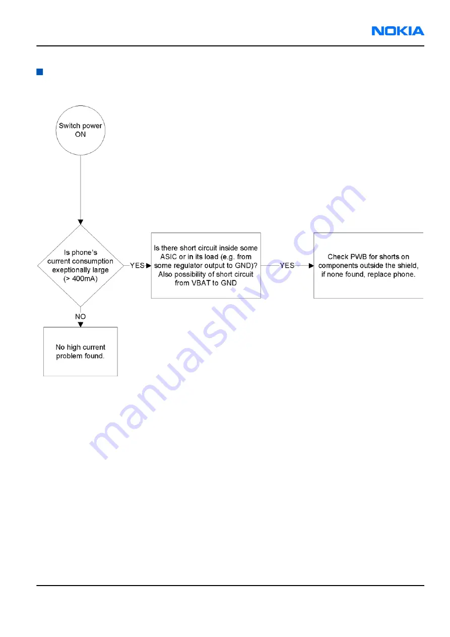
Page 109: ...eral power checking troubleshooting Troubleshooting flow RM 88 BB Troubleshooting and Manual Tuning Guide Nokia Customer Care Issue 1 COMPANY CONFIDENTIAL Page 6 7 Copyright 2006 Nokia All rights reserved ...
Page 110: ... current measuring fault troubleshooting Troubleshooting flow RM 88 Nokia Customer Care BB Troubleshooting and Manual Tuning Guide Page 6 8 COMPANY CONFIDENTIAL Issue 1 Copyright 2006 Nokia All rights reserved ...
Page 111: ... of the BSI signal Keyboard troubleshooting Context There are two possible failure modes in the keyboard module One or more keys can be stuck so that the key does not react when a keydome is pressed This kind of failure is caused by mechanical reasons dirt corrosion RM 88 BB Troubleshooting and Manual Tuning Guide Nokia Customer Care Issue 1 COMPANY CONFIDENTIAL Page 6 9 Copyright 2006 Nokia All r...
Page 112: ... more detailed description of the keyboard and keymatrix see section Keyboard in System Module If the failure mode is not clear start with the Keyboard Test in Phoenix Troubleshooting flow RM 88 Nokia Customer Care BB Troubleshooting and Manual Tuning Guide Page 6 10 COMPANY CONFIDENTIAL Issue 1 Copyright 2006 Nokia All rights reserved ...
Page 113: ...USB interface troubleshooting Troubleshooting flow RM 88 BB Troubleshooting and Manual Tuning Guide Nokia Customer Care Issue 1 COMPANY CONFIDENTIAL Page 6 11 Copyright 2006 Nokia All rights reserved ...
Page 114: ...Charging troubleshooting Troubleshooting flow RM 88 Nokia Customer Care BB Troubleshooting and Manual Tuning Guide Page 6 12 COMPANY CONFIDENTIAL Issue 1 Copyright 2006 Nokia All rights reserved ...
Page 115: ...Dead or jammed troubleshooting Troubleshooting flow RM 88 BB Troubleshooting and Manual Tuning Guide Nokia Customer Care Issue 1 COMPANY CONFIDENTIAL Page 6 13 Copyright 2006 Nokia All rights reserved ...
Page 116: ...IrDA troubleshooting Troubleshooting flow RM 88 Nokia Customer Care BB Troubleshooting and Manual Tuning Guide Page 6 14 COMPANY CONFIDENTIAL Issue 1 Copyright 2006 Nokia All rights reserved ...
Page 117: ...Vibra troubleshooting Troubleshooting flow RM 88 BB Troubleshooting and Manual Tuning Guide Nokia Customer Care Issue 1 COMPANY CONFIDENTIAL Page 6 15 Copyright 2006 Nokia All rights reserved ...
Page 118: ...MiniSD troubleshooting Troubleshooting flow RM 88 Nokia Customer Care BB Troubleshooting and Manual Tuning Guide Page 6 16 COMPANY CONFIDENTIAL Issue 1 Copyright 2006 Nokia All rights reserved ...
Page 119: ...SIM troubleshooting Troubleshooting flow RM 88 BB Troubleshooting and Manual Tuning Guide Nokia Customer Care Issue 1 COMPANY CONFIDENTIAL Page 6 17 Copyright 2006 Nokia All rights reserved ...
Page 120: ...phone is on as it does when the phone is off The backlight can be on in some cases Image on the display not correct Image on the display can be corrupted or a part of the image can be missing If a part of the image is missing change the display module If the image is otherwise corrupted follow the appropriate troubleshooting diagram Backlight dim or not working at all Backlight LED components are ...
Page 121: ...allowed Two single dot defects that are within 5 mm of each other should be interpreted as combined dot defect Note Blinking pixels are not allowed in normal operating temperatures and light conditions RM 88 BB Troubleshooting and Manual Tuning Guide Nokia Customer Care Issue 1 COMPANY CONFIDENTIAL Page 6 19 Copyright 2006 Nokia All rights reserved ...
Page 122: ...Display fault troubleshooting Troubleshooting flow RM 88 Nokia Customer Care BB Troubleshooting and Manual Tuning Guide Page 6 20 COMPANY CONFIDENTIAL Issue 1 Copyright 2006 Nokia All rights reserved ...
Page 123: ...ent Light Sensor ALS You can enable disable ALS with the help of Phoenix service software Display brightness can be adjusted manually if ALS is disabled If the ambient light sensor is enabled it adjusts the display brightness automatically RM 88 BB Troubleshooting and Manual Tuning Guide Nokia Customer Care Issue 1 COMPANY CONFIDENTIAL Page 6 21 Copyright 2006 Nokia All rights reserved ...
Page 124: ...Troubleshooting flow RM 88 Nokia Customer Care BB Troubleshooting and Manual Tuning Guide Page 6 22 COMPANY CONFIDENTIAL Issue 1 Copyright 2006 Nokia All rights reserved ...
Page 125: ...ubleshooting page 6 20 LED driver troubleshooting page 6 28 ALS troubleshooting page 6 25 RM 88 BB Troubleshooting and Manual Tuning Guide Nokia Customer Care Issue 1 COMPANY CONFIDENTIAL Page 6 23 Copyright 2006 Nokia All rights reserved ...
Page 126: ...L backlight fault troubleshooting Troubleshooting flow RM 88 Nokia Customer Care BB Troubleshooting and Manual Tuning Guide Page 6 24 COMPANY CONFIDENTIAL Issue 1 Copyright 2006 Nokia All rights reserved ...
Page 127: ...s for ALS troubleshooting the following troubleshooting diagram refers to these Phoenix LED control tool also shows you luminance The correct luminance in darkness is 20 lx and in office environment 100 2000 lx The luminance value depends strongly on the light source and the angle of the phone so these values are only a rough guideline LED driver control voltage measurement points can be found fro...
Page 128: ...r Calibration window 5 In the Pull Up Resistor Calibration pane click Start and Write 6 In the Ambient Light Sensor Calibration pane check the Use default values only check box and click Write 7 To end the calibration click Close RM 88 Nokia Customer Care BB Troubleshooting and Manual Tuning Guide Page 6 26 COMPANY CONFIDENTIAL Issue 1 Copyright 2006 Nokia All rights reserved ...
Page 129: ...Troubleshooting flow RM 88 BB Troubleshooting and Manual Tuning Guide Nokia Customer Care Issue 1 COMPANY CONFIDENTIAL Page 6 27 Copyright 2006 Nokia All rights reserved ...
Page 130: ...LED driver troubleshooting Troubleshooting flow RM 88 Nokia Customer Care BB Troubleshooting and Manual Tuning Guide Page 6 28 COMPANY CONFIDENTIAL Issue 1 Copyright 2006 Nokia All rights reserved ...
Page 131: ...enix Steps 1 Start Phoenix service software 2 From the File menu choose Open Product and then choose the correct type designator from the Product list 3 Place the phone to a flash adapter in the local mode 4 Choose Testing Bluetooth LOCALS 5 Locate JBT 9 s serial number 12 digits found in the type label on the back of JBT 9 In addition to JBT 9 also SB 6 JBT 3 and JBT 6 Bluetooth test boxes can be...
Page 132: ...er 4 From the Mode drop down menu set mode to Local 5 Choose Testing Self Tests 6 In the Self Tests window check the following Bluetooth related tests ST_LPRF_IF_TEST ST_LPRF_AUDIO_LINES_TEST ST_BT_WAKEUP_TEST RM 88 Nokia Customer Care BB Troubleshooting and Manual Tuning Guide Page 6 30 COMPANY CONFIDENTIAL Issue 1 Copyright 2006 Nokia All rights reserved ...
Page 133: ...he tests click Start Figure 38 Bluetooth self tests in Phoenix RM 88 BB Troubleshooting and Manual Tuning Guide Nokia Customer Care Issue 1 COMPANY CONFIDENTIAL Page 6 31 Copyright 2006 Nokia All rights reserved ...
Page 134: ...etooth BER failure troubleshooting Troubleshooting flow RM 88 Nokia Customer Care BB Troubleshooting and Manual Tuning Guide Page 6 32 COMPANY CONFIDENTIAL Issue 1 Copyright 2006 Nokia All rights reserved ...
Page 135: ...BT audio failure troubleshooting Troubleshooting flow RM 88 BB Troubleshooting and Manual Tuning Guide Nokia Customer Care Issue 1 COMPANY CONFIDENTIAL Page 6 33 Copyright 2006 Nokia All rights reserved ...
Page 136: ...piece External microphone to Internal handsfree speaker Internal microphone to External earpiece Each audio loop sets routing from the specified input to the specified output enabling a quick in out test Loop path gains are fixed and they cannot be changed using Phoenix Correct pins and signals for each test are presented in the following table Phoenix audio loop tests and test results The results...
Page 137: ...o External Earpiece B2100 OUT GND XEARL and GND 35 100 1360 0 NA XEARR and GND Measurement data Figure 39 Single ended output waveform of the Ext_in_HP_out measurement when earpiece is connected Figure 40 Differential output waveform of the Ext_in_IHF_out out loop measurement when speaker is connected RM 88 BB Troubleshooting and Manual Tuning Guide Nokia Customer Care Issue 1 COMPANY CONFIDENTIAL...
Page 138: ...ed output waveform of the HP_in_Ext_out loop when microphone is connected RM 88 Nokia Customer Care BB Troubleshooting and Manual Tuning Guide Page 6 36 COMPANY CONFIDENTIAL Issue 1 Copyright 2006 Nokia All rights reserved ...
Page 139: ...nternal earpiece troubleshooting Troubleshooting flow RM 88 BB Troubleshooting and Manual Tuning Guide Nokia Customer Care Issue 1 COMPANY CONFIDENTIAL Page 6 37 Copyright 2006 Nokia All rights reserved ...
Page 140: ...ternal microphone troubleshooting Troubleshooting flow RM 88 Nokia Customer Care BB Troubleshooting and Manual Tuning Guide Page 6 38 COMPANY CONFIDENTIAL Issue 1 Copyright 2006 Nokia All rights reserved ...
Page 141: ...IHF troubleshooting Troubleshooting flow RM 88 BB Troubleshooting and Manual Tuning Guide Nokia Customer Care Issue 1 COMPANY CONFIDENTIAL Page 6 39 Copyright 2006 Nokia All rights reserved ...
Page 142: ...ternal microphone troubleshooting Troubleshooting flow RM 88 Nokia Customer Care BB Troubleshooting and Manual Tuning Guide Page 6 40 COMPANY CONFIDENTIAL Issue 1 Copyright 2006 Nokia All rights reserved ...
Page 143: ...xternal earpiece troubleshooting Troubleshooting flow RM 88 BB Troubleshooting and Manual Tuning Guide Nokia Customer Care Issue 1 COMPANY CONFIDENTIAL Page 6 41 Copyright 2006 Nokia All rights reserved ...
Page 144: ...d reproduced from the IHF speakers radiates from the sound holes on the bottom of the lower block The hole of the microphone is located between the upper and the lower block on the right side For a correct functionality of the phone all sound holes must be always open When the phone is used care must be taken not to close any of those holes with a hand or fingers The phone should be dry and clean ...
Page 145: ...Earpiece troubleshooting Troubleshooting flow RM 88 BB Troubleshooting and Manual Tuning Guide Nokia Customer Care Issue 1 COMPANY CONFIDENTIAL Page 6 43 Copyright 2006 Nokia All rights reserved ...
Page 146: ...Acoustics IHF troubleshooting Troubleshooting flow RM 88 Nokia Customer Care BB Troubleshooting and Manual Tuning Guide Page 6 44 COMPANY CONFIDENTIAL Issue 1 Copyright 2006 Nokia All rights reserved ...
Page 147: ...Microphone troubleshooting Troubleshooting flow RM 88 BB Troubleshooting and Manual Tuning Guide Nokia Customer Care Issue 1 COMPANY CONFIDENTIAL Page 6 45 Copyright 2006 Nokia All rights reserved ...
Page 148: ...tion has to be performed before other item s However if all calibrations are selected at the same time there is no need to perform the ADC calibration first 8 Click Calibrate The calibration of the selected item s is carried out automatically The candidates for the new calibration values are shown in the Calculated values column If the new calibration values seem to be acceptable please refer to t...
Page 149: ...7 RF Troubleshooting and Manual Tuning Guide Nokia Customer Care Issue 1 COMPANY CONFIDENTIAL Page 7 1 Copyright 2006 Nokia All rights reserved ...
Page 150: ...RM 88 Nokia Customer Care RF Troubleshooting and Manual Tuning Guide This page left intentionally blank Page 7 2 COMPANY CONFIDENTIAL Issue 1 Copyright 2006 Nokia All rights reserved ...
Page 151: ...ings 7 21 Rx calibration GSM 7 21 Rx band filter response compensation GSM 7 25 GSM transmitter tunings 7 30 Tx IQ tuning GSM 7 30 Tx power level tuning GSM 7 32 List of Tables Table 12 Rf channel filter calibration tuning limits 7 20 Table 13 RF tuning limits in Rx calibration 7 24 List of Figures Figure 42 RM 88 RF components 7 6 Figure 43 RM 88 BT component placement 7 7 Figure 44 RM 88 compone...
Page 152: ...RM 88 Nokia Customer Care RF Troubleshooting and Manual Tuning Guide This page left intentionally blank Page 7 4 COMPANY CONFIDENTIAL Issue 1 Copyright 2006 Nokia All rights reserved ...
Page 153: ...requency signals The RF section of the phone is around RF ASIC N7505 TX FEM N7520 and all of this RF section is built inside of non removable shields A7506 A7507 Therefore the engine will be replaced after carefully checked power and receiver tuning at antenna port RF key component placement RM 88 RF Troubleshooting and Manual Tuning Guide Nokia Customer Care Issue 1 COMPANY CONFIDENTIAL Page 7 5 ...
Page 154: ...Figure 42 RM 88 RF components RM 88 Nokia Customer Care RF Troubleshooting and Manual Tuning Guide Page 7 6 COMPANY CONFIDENTIAL Issue 1 Copyright 2006 Nokia All rights reserved ...
Page 155: ...Figure 43 RM 88 BT component placement RM 88 RF Troubleshooting and Manual Tuning Guide Nokia Customer Care Issue 1 COMPANY CONFIDENTIAL Page 7 7 Copyright 2006 Nokia All rights reserved ...
Page 156: ...8 component placement top Figure 45 RM 88 component placement bottom RM 88 Nokia Customer Care RF Troubleshooting and Manual Tuning Guide Page 7 8 COMPANY CONFIDENTIAL Issue 1 Copyright 2006 Nokia All rights reserved ...
Page 157: ... reg pass switch to ON position 3 Connect an RF cable between the RF connector of the module test jig MJ 67 and measurement equipment or alternatively use a 50 ohms at least 2 W dummy load in the module test jig RF connector otherwise GSM may be damaged Note Make sure that all connections are made to the correct RF connector 4 Set Rx on i Set the phone module to the test jig and start Phoenix serv...
Page 158: ... GSM Rx chain activation for manual measurements GSM RSSI measurement Context RSSI signal measurement is the main Rx troubleshooting measurement The test measures the strength of the received signal Steps 1 Start Phoenix service software 2 Choose Testing GSM RSSI Reading 3 Set the RF signal generator for channel frequency 67 771 kHz CW mode with 80 dBm signal Alternatively set the cellular tester ...
Page 159: ...GSM transmitter testing is RF Controls Remember that retuning is not a fix Phones are tuned correctly in production The first set of steps instructs how to assemble the test setup This setup is general for all Tx troubleshooting tasks Alternative steps provide specific troubleshooting instructions for Phoenix service software Caution Never activate the GSM transmitter without a proper antenna load...
Page 160: ... analyzer input 4 Set Tx on i Set the phone module to the test jig and start Phoenix service software ii Initialize connection to the phone With FPS 10 use FBUS driver when using DAU 9S and COMBOX driver iii From the File menu choose product File Choose Product xx x type designator of the phone iv From the toolbar set operating mode to Local 5 EGSM900 GSM850 1800 1900 troubleshooting i From the Te...
Page 161: ...Figure 48 RF Controls window RM 88 RF Troubleshooting and Manual Tuning Guide Nokia Customer Care Issue 1 COMPANY CONFIDENTIAL Page 7 13 Copyright 2006 Nokia All rights reserved ...
Page 162: ...TX 850 900 troubleshooting Troubleshooting flow RM 88 Nokia Customer Care RF Troubleshooting and Manual Tuning Guide Page 7 14 COMPANY CONFIDENTIAL Issue 1 Copyright 2006 Nokia All rights reserved ...
Page 163: ...tenna functionality The main antenna has one antenna GSM In the GSM antenna there is one Feed and two GND contacts RM 88 RF Troubleshooting and Manual Tuning Guide Nokia Customer Care Issue 1 COMPANY CONFIDENTIAL Page 7 15 Copyright 2006 Nokia All rights reserved ...
Page 164: ... the RDC 0 ohm short circuit Figure 49 Main antenna Figure 50 Feed and GND spots of the main antenna RM 88 Nokia Customer Care RF Troubleshooting and Manual Tuning Guide Page 7 16 COMPANY CONFIDENTIAL Issue 1 Copyright 2006 Nokia All rights reserved ...
Page 165: ...nd understand the measurement setup In the following table there are RF attenuations of the module jig Band Attenuation GSM850 0 2 dB GSM900 0 2 dB GSM1800 0 3 dB GSM1900 0 6 dB RF autotuning Prerequisites For information on the recommended test set up refer to the corresponding information on PWS NOL Before you can use the auto tune feature the GPIB driver from the GPIB card vendor must be instal...
Page 166: ... list of found Listeners 5 To specify the cable loss from module jig to the communication tester choose Set Loss from the Tuning menu 6 Click the Cable tab and add the extra cable attenuation Note Cable losses have to be determined on the basis of a cable used RM 88 Nokia Customer Care RF Troubleshooting and Manual Tuning Guide Page 7 18 COMPANY CONFIDENTIAL Issue 1 Copyright 2006 Nokia All rights...
Page 167: ...indow see that the Enable showing of messages check box is checked then click OK 10 To complete the RF autotuning click OK Results Autotuning completed successfully message appears RM 88 RF Troubleshooting and Manual Tuning Guide Nokia Customer Care Issue 1 COMPANY CONFIDENTIAL Page 7 19 Copyright 2006 Nokia All rights reserved ...
Page 168: ... Tx filter 0 10 31 Rx filter 0 16 31 Steps 1 From the Operating mode drop down menu set mode to Local 2 Choose Tuning Rf Channel Filter Calibration 3 Click Tune 4 To save the values to the PMM Phone Permanent Memory area click Write 5 To close the Rf Channel Filter Calibration window click Close Results Figure 51 Rf channel filter calibration typical values RM 88 Nokia Customer Care RF Troubleshoo...
Page 169: ...lose GSM receiver tunings Rx calibration GSM Context Rx Calibration is used to find out the real gain values of the GSM Rx AGC system and tuning response of the AFC system AFC D A init value and AFC slope Steps 1 Connect the GSM connector of the module jig to a signal generator 2 Start Phoenix service software 3 From the Operating mode drop down menu set mode to Local 4 Choose Tuning GSM Rx Calibr...
Page 170: ...7 Click Start RM 88 Nokia Customer Care RF Troubleshooting and Manual Tuning Guide Page 7 22 COMPANY CONFIDENTIAL Issue 1 Copyright 2006 Nokia All rights reserved ...
Page 171: ...n with band EGSM900 pop up window Important The calibration uses a non modulated CW signal Increase the signal generator level by cable attenuation and module jig probe attenuation RM 88 RF Troubleshooting and Manual Tuning Guide Nokia Customer Care Issue 1 COMPANY CONFIDENTIAL Page 7 23 Copyright 2006 Nokia All rights reserved ...
Page 172: ...ax Unit GSM850 AFC Value 200 105 62 200 AFC slope 0 122 200 RSSI0 106 107 110 114 dB GSM900 AFC Value 200 105 62 200 AFC slope 0 122 200 RSSI0 106 107 110 114 dB GSM1800 RSSI0 104 104 109 114 dB GSM1900 RSSI0 104 104 109 114 dB RM 88 Nokia Customer Care RF Troubleshooting and Manual Tuning Guide Page 7 24 COMPANY CONFIDENTIAL Issue 1 Copyright 2006 Nokia All rights reserved ...
Page 173: ...ejecting filter in front of RF ASIC front end The amplitude ripple caused by these filters causes ripple to the RSSI measurement and therefore calibration is needed The calibration has to be repeated for each GSM band Steps 1 Connect module jig s GSM connector to signal generator 2 From the dropdown menus set Operating mode to Local System mode to GSM and Band to GSM900 RM 88 RF Troubleshooting an...
Page 174: ...nse Compensation 4 Check Manual and Load from Phone check boxes Clear Save to Phone check box 5 Click Start RM 88 Nokia Customer Care RF Troubleshooting and Manual Tuning Guide Page 7 26 COMPANY CONFIDENTIAL Issue 1 Copyright 2006 Nokia All rights reserved ...
Page 175: ... instructed in the Rx Band Filter Response Compensation for EGSM900 popup window 8 To perform tuning click OK 9 Go through all 9 frequencies RM 88 RF Troubleshooting and Manual Tuning Guide Nokia Customer Care Issue 1 COMPANY CONFIDENTIAL Page 7 27 Copyright 2006 Nokia All rights reserved ...
Page 176: ... 3 0 5 dB Ch 251 893 86771 MHz 3 0 5 dB Ch 261 895 86771 MHz 10 1 5 dB GSM900 Ch 965 923 26771 MHz 10 1 5 dB Ch 975 925 26771 MHz 3 0 5 dB Ch 987 927 66771 MHz 3 0 5 dB Ch 1009 932 06771 MHz 3 0 5 dB Ch 37 942 46771 MHz 3 0 5 dB Ch 90 953 06771 MHz 3 0 5 dB Ch 114 957 86771 MHz 3 0 5 dB Ch 124 959 86771 MHz 3 0 5 dB Ch 136 962 26771 MHz 10 1 5 dB GSM1800 RM 88 Nokia Customer Care RF Troubleshootin...
Page 177: ...h 908 1884 46771 MHz 10 1 5 dB GSM1900 Ch 496 1927 06771 MHz 10 1 5 dB Ch 512 1930 26771 MHz 3 0 5 dB Ch 537 1935 26771 MHz 3 0 5 dB Ch 586 1945 06771 MHz 3 0 5 dB Ch 661 1960 06771 MHz 3 0 5 dB Ch 736 1975 06771 MHz 3 0 5 dB Ch 794 1986 66771 MHz 3 0 5 dB Ch 810 1989 86771 MHz 3 0 5 dB Ch 835 1994 86771 MHz 10 1 5 dB RM 88 RF Troubleshooting and Manual Tuning Guide Nokia Customer Care Issue 1 COM...
Page 178: ...ignal paths Tx IQ tuning tuning balances the I and Q branches Tx IQ tuning must be performed on all GSM bands Steps 1 From the dropdown menus set Operating mode to Local System mode to GSM and Band to GSM900 2 From the Tuning menu choose GSM Tx IQ Tuning 3 Set Mode to Automatic and Edge to Off 4 Click Start Wait until automatic tuning has finished and moved the sliders Values are written to the ph...
Page 179: ...ing window click Close Next actions Tuning sliders should be close to the center of the scale after the tuning and within the limits specified in the table below If they are not within the limits check Tx IQ quality manually Min Typ Max Unit GSM850 I DC offset Q DC offset 6 4 6 Ampl 1 0 1 dB Phase 85 90 95 GSM900 RM 88 RF Troubleshooting and Manual Tuning Guide Nokia Customer Care Issue 1 COMPANY ...
Page 180: ...PA gain and hence the power levels have to be aligned separately for EDGE transmission Tx power level tuning has to be performed on all GSM bands Steps 1 Connect the phone to a spectrum analyzer 2 From the dropdown menus set Operating mode to Local System mode to GSM and Band to GSM900 3 From the Tuning menu choose GSM Tx Power Level Tuning 4 Set Mode to Automatic and Edge to Off 5 Set the spectru...
Page 181: ... detector can be also used Remember to take the attenuations in the account 6 Click Start 7 Adjust power levels 5 15 and 19 to correspond the Target dBm column by pressing or keys RM 88 RF Troubleshooting and Manual Tuning Guide Nokia Customer Care Issue 1 COMPANY CONFIDENTIAL Page 7 33 Copyright 2006 Nokia All rights reserved ...
Page 182: ... 0 35 0 419 0 6 PL15 coefficient 0 247 PL19 coefficient 0 12 0 204 0 3 GSM900 EDGE off PL5 coefficient 0 45 0 626 0 73 PL15 coefficient 0 234 PL19 coefficient 0 12 0 195 0 3 GSM900 EDGE on PL8 coefficient 0 35 0 419 0 6 PL15 coefficient 0 247 PL19 coefficient 0 12 0 204 0 3 GSM1800 EDGE off PL0 coefficient 0 45 0 51 0 7 RM 88 Nokia Customer Care RF Troubleshooting and Manual Tuning Guide Page 7 34...
Page 183: ...11 coefficient 0 218 PL15 coefficient 0 12 0 184 0 3 GSM1900 EDGE on PL2 coefficient 0 35 0 377 0 6 PL11 coefficient 0 23 PL15 coefficient 0 12 0 193 0 3 If the values are within the limits check that the Save to Phone Permanent Memory check box is checked and click Stop RM 88 RF Troubleshooting and Manual Tuning Guide Nokia Customer Care Issue 1 COMPANY CONFIDENTIAL Page 7 35 Copyright 2006 Nokia...
Page 184: ...lated by clicking the Calculate Coefficients button Check the coefficients against the RF tuning limits table presented in Step 9 12 When the tuning is completed click Stop Next actions Repeat steps 4 to 9 for GSM1800 and GSM1900 On those bands only power levels 0 11 and 15 need to be tuned RM 88 Nokia Customer Care RF Troubleshooting and Manual Tuning Guide Page 7 36 COMPANY CONFIDENTIAL Issue 1 ...
Page 185: ...8 System Module Nokia Customer Care Issue 1 COMPANY CONFIDENTIAL Page 8 1 Copyright 2006 Nokia All rights reserved ...
Page 186: ...RM 88 Nokia Customer Care System Module This page left intentionally blank Page 8 2 COMPANY CONFIDENTIAL Issue 1 Copyright 2006 Nokia All rights reserved ...
Page 187: ...eaker 8 19 Vibra circuitry 8 19 Baseband technical specifications 8 20 External interfaces 8 20 USB IF electrical characteristics 8 20 FBUS interface electrical characteristics between RAP and N2300 8 21 SIM IF connections 8 21 MiniSD interface connections 8 22 Charger connector and charging interface connections electrical characteristics 8 23 Battery interface electrical characteristics 8 24 Int...
Page 188: ...ram 8 6 Figure 53 Power distribution diagram 8 9 Figure 54 BT RAP connection 8 11 Figure 55 MiniSD contact area pin order 8 14 Figure 56 Battery pin order 8 15 Figure 57 ALS HW implementation 8 16 Figure 58 E mail LED implementation 8 17 Figure 59 Audio block diagram 8 18 Figure 60 Internal microphone passive circuitry 8 18 Figure 61 Internal earpiece circuitry 8 19 Figure 62 Internal speaker circ...
Page 189: ...e CeBBo1GSM BB Ritsa 4 5 RF The baseband includes following HW blocks RAP GSM EDGE BaseBand ASIC ARM926EJ S MCU Lead3 PH3 DSP N2200 primary Energy Management ASIC N2300 secondary Energy Management ASIC T combo memory 256Mbit NOR FLASH 256Mbit DDR SDRAM 1Gbit Mux one Nand combo memory Audio Microphone Speaker IHF and external audio EL keyboard backlightning Ambient light sensor Bottom Connectors Mi...
Page 190: ...s the power up and power down routines of the system During the times when the digital BB is alive N2200 handles a variety of tasks that can not be accomplished elsewhere due to voltage requirements noise etc N2300 power IC is intended for energy management control supply voltage generation and charge control of mobile phone N2300 has a step down type buck programmable switch mode regulator for di...
Page 191: ...the same as PWR_OFF warm but the RTC and the oscillator are off RESET RESET mode is a synonym for start up sequence In this mode certain regulators are enabled and after they and RFClk have stabilized the system reset PurX is released and PWR_ON mode entered RESET mode uses 32 kHz clock to count the REST mode delay typically 16 ms DEEP SLEEP Deep sleep mode is entered only from Pwr_on mode with th...
Page 192: ... of SW Operation modes There are four different power up possibilities to switch power on Power key is pressed Charger is connected A pulse is supplied to MBUS line Clk Internal power up with Real Time Clock alarm Power is not switched on by supplying battery voltage as in DCT4 generations It should be noted that system behavior depends on the type of device the engine is in The difference is main...
Page 193: ...up procedure starts when the user presses power key option 1 or when not empty battery is attached option 2 In addition some other triggers may start the system RM 88 System Module Nokia Customer Care Issue 1 COMPANY CONFIDENTIAL Page 8 9 Copyright 2006 Nokia All rights reserved ...
Page 194: ...cy sleep clock instead of RF clock In deep sleep ASIC is sleep mode and therefore VCTCXO can be switched off VCTCXO is a significant power consumer In deep sleep also the core voltage is decreased Bluetooth The device uses BTH Perf2 3 solution The Bluetooth is V 2 0 EDR The Bluetooth module is implemented by using CSR s BC4 ROM BlueCore 4 ROM is a single chip radio and baseband IC for Bluetooth 2 ...
Page 195: ... or receiving but not both at once USB USB Universal Serial Bus provides a wired connectivity between a USB host PC and peripheral devices USB is a differential serial bus for USB devices USB controller supports USB specification revision 2 0 with full speed USB 12 Mbps The device is connected to the USB host through the system connector The USB bus is hot plugged capable which means that USB devi...
Page 196: ...fiers The TXC bus includes TxCCtrl pin which is used to select the EM ASIC N2200 DAC the data is written to In case the TxCCtrl is in low state the data is written to the DAC1 and in case the TxCCtrl is in high state the data is written to DAC2 The TxC bus clock frequency is programmable but the frequency to be used in CeBBo1 is 19 2 MHz and for RFBUS the frequency used is 9 6 MHz FBUS USB and FBU...
Page 197: ...and SIM contacts The EM ASIC SIM1 interface supports both 1 8 V and 3 0 V SIM cards The SIM interface voltage is first 1 8 V when the SIM card is inserted and if the card does not response to the ATR a 3 V interface voltage is used MiniSD interface In the RAP the MMC SD interface is multiplexed with NAND Flash and SIM2 interfaces RM 88 System Module Nokia Customer Care Issue 1 COMPANY CONFIDENTIAL...
Page 198: ...le battery interface The interface consists of three connectors VBAT BSI and GND The BSI line is used to recognize the battery capacity by a battery internal pull down resistor RM 88 Nokia Customer Care System Module Page 8 14 COMPANY CONFIDENTIAL Issue 1 Copyright 2006 Nokia All rights reserved ...
Page 199: ...gine qwerty keyboard matrix The communication between COP8 and RAP is handled by I2C bus Display and keyboard backlight The device has one LED Driver SMPS that is used to drive six display LEDs Display LEDs are connected in to two three LED series Current adjustment of the driver is done from the display LED branch and keyboard current also depends on the display brightness In a typical use case k...
Page 200: ...ternal NTC resistor N2200 reads the light sensor LS and temperature LST results ALS calibration is not possible in the service points ALS is serviced by replacing faulty phototransistors Figure 57 ALS HW implementation Table 15 ALS resistor values Symbol R1 R2 R3 R4 R5 R6 R7 NTC res Value 5 kOhm 15 kOhm 30 kOhm 50 kOhm 470 kOhm 100 kohm 470 kohm 47 kOhm E Mail LED The device has E Mail indicator L...
Page 201: ...ated into RAP and analogue functions into EM ASIC N2200 Audio codec supports 48 kHz and 44 1 kHz sampling rates in addition to 40 kHz which provides full 20 kHz audio bandwidth near CD quality in Rx path RM 88 System Module Nokia Customer Care Issue 1 COMPANY CONFIDENTIAL Page 8 17 Copyright 2006 Nokia All rights reserved ...
Page 202: ...ternal HandsFree IHF call modes An analogue electret microphone is connected to Retu ASIC s Mic1P and Mic1N is connected ground near Retu Figure 60 Internal microphone passive circuitry RM 88 Nokia Customer Care System Module Page 8 18 COMPANY CONFIDENTIAL Issue 1 Copyright 2006 Nokia All rights reserved ...
Page 203: ...F call mode A dynamic 20 mm speaker is connected to N2200 ASIC s outputs HFSpP and HFSpN The IHF amplifier integrated in EM ASIC N2200 is a Digital Pulse Modulated Amplifier DPMA Figure 62 Internal speaker circuitry Vibra circuitry Vibra is used for vibra alarm function The vibra motor is connected to the N2200 ASIC VibraP and VibraN Pulse Width Modulated PWM outputs RM 88 System Module Nokia Cust...
Page 204: ...arameter Min Max Unit Notes Absolute maximum voltage on D and D VD D 1 4 6 V USB specification revision 2 0 Supply voltage VBUS 4 4 5 25 V Supply current Functioning IVBUS 100 mA Suspended IVBUS 500 uA Unconfigured IVBUS 100 mA High level input voltage V High driven VIH 2 High floating VIHZ 2 7 3 6 Low level input voltage VIL 0 8 V RM 88 Nokia Customer Care System Module Page 8 20 COMPANY CONFIDEN...
Page 205: ...V2 VDDSHV2 V Low level Input voltage VIL 0 0 3 x VDDSHV2 V High level output voltage VOH 0 8 x VDDSHV2 VDDSHV2 V Low level output voltage VOL 0 0 22 x VDDSHV2 V Rise fall time tR tF 0 25 ns VDDSHV2 1 8V SIM IF connections Pin Signal I O Engine connection Notes C1 VSIM Out N2200 VSIM1 Supply voltage to SIM card 1 8 V or 3 0 V C2 SIMRST Out N2200 SIM1Rst Reset signal to SIM card C3 SIMCLK Out N2200 ...
Page 206: ...tdow n GenIO 10 SDDa2 0 1 8 V 0 3 6V Data bit 1 GenIO 14 SDDa3 0 1 8 V 0 3 6V Data bit 2 GenIO 15 SDDa4 0 1 8 V 0 3 6V Data bit 3 GenIO 12 or GenIO 65 MMCCmd Dir 0 1 8 V 0 3 6V Comman d Dir GenIO 11 or GenIO 66 MMCDaDir 0 1 8 V 0 3 6V Data bit 0 Dir GenIO 03 SDDaDir2 0 1 8 V 0 3 6V Data bit 1 Dir GenIO 04 SDDaDir3 0 1 8 V 0 3 6V Data bit 2 Dir GenIO 05 SDDaDir4 0 1 8 V 0 3 6V Data bit 3 Dir GenIO ...
Page 207: ...al characteristics Figure 64 Charger connector Table 16 Charging interface connections Pin Signal I O Engine connection Notes 1 Vchar In N2300 VCharIn1 2 Charging voltage charger detection Center pin 2 Charge GND Ground Charger ground Table 17 Charging IF electrical characteristics Description Parameter Min Max Unit Notes Vchar V Charge 0 9 V Center pin Vchar I Charge 0 85 A Center pin Charge GND ...
Page 208: ...y X4400 ALS V4400 Vibra M2100 Microphone B2100 Earpiece B2101 IHF speaker B2102 l2C I2C is an Inter IC bus and aimed for slow control of peripherals The device uses I2C to interconnect QWERTY keyboard controller to RAP Keyboard interface electrical characteristics Description Parameter Min Typ Max Unit Notes High level input voltage VIH 0 65 VDDS VDDS 0 3 VDDS V Row Low level input voltage VIL 0 3...
Page 209: ...EM ASIC N2300 2 V LED2 N2301 VLEDout N2301 is controlled by EM ASIC N2300 3 VDD EM ASIC N2200 VAUX Core Voltage 4 GND 5 RDX RAP Lcdrdx Read Enable active low 6 D CX RAP Lcdrmd Data Command select high data low command 7 D1 RAP Lcdda1 Data 8 D3 RAP Lcdda3 Data 9 GND RM 88 System Module Nokia Customer Care Issue 1 COMPANY CONFIDENTIAL Page 8 25 Copyright 2006 Nokia All rights reserved ...
Page 210: ...C N2200 VIO Interface voltage 23 V LED2 R2303 SETCURR1 Resistor 24 V LED1 R2303 SETCURR1 Resistor Back up battery interface electrical characteristics Table 19 Back up battery connections Pin name I O Connection Notes L2207 VBack N2200 VBack Back up battery G2200 is connected to N2200 via coil Table 20 Back up battery electrical characteristics Description Parameter Min Typ Max Unit Back Up Batter...
Page 211: ...Frequency mappings GSM850 frequencies RM 88 System Module Nokia Customer Care Issue 1 COMPANY CONFIDENTIAL Page 8 27 Copyright 2006 Nokia All rights reserved ...
Page 212: ...EGSM900 frequencies RM 88 Nokia Customer Care System Module Page 8 28 COMPANY CONFIDENTIAL Issue 1 Copyright 2006 Nokia All rights reserved ...
Page 213: ...GSM1800 frequencies RM 88 System Module Nokia Customer Care Issue 1 COMPANY CONFIDENTIAL Page 8 29 Copyright 2006 Nokia All rights reserved ...
Page 214: ...GSM1900 frequencies RM 88 Nokia Customer Care System Module Page 8 30 COMPANY CONFIDENTIAL Issue 1 Copyright 2006 Nokia All rights reserved ...
Page 215: ...9 Schematics Nokia Customer Care Issue 1 COMPANY CONFIDENTIAL Page 9 1 Copyright 2006 Nokia All rights reserved ...
Page 216: ...RM 88 Nokia Customer Care Schematics This page left intentionally blank Page 9 2 COMPANY CONFIDENTIAL Issue 1 Copyright 2006 Nokia All rights reserved ...
Page 217: ...ooth 9 8 UI part 1 9 9 UI part 2 9 10 RF part 9 11 Audio IHF Vibra 9 12 SIM interface 9 13 IrDA interface 9 14 MMC interface 9 15 CMT memories 9 16 Camera 9 17 RM 88 Schematics Nokia Customer Care Issue 1 COMPANY CONFIDENTIAL Page 9 3 Copyright 2006 Nokia All rights reserved ...
Page 218: ...System connector RM 88 Schematics Nokia Customer Care Issue 1 COMPANY CONFIDENTIAL Page 9 4 Copyright 2006 Nokia All rights reserved ...
Page 219: ...RETU RM 88 Schematics Nokia Customer Care Issue 1 COMPANY CONFIDENTIAL Page 9 5 Copyright 2006 Nokia All rights reserved ...
Page 220: ...TAHVO RM 88 Schematics Nokia Customer Care Issue 1 COMPANY CONFIDENTIAL Page 9 6 Copyright 2006 Nokia All rights reserved ...
Page 221: ...RAPGSM RM 88 Schematics Nokia Customer Care Issue 1 COMPANY CONFIDENTIAL Page 9 7 Copyright 2006 Nokia All rights reserved ...
Page 222: ...Bluetooth RM 88 Schematics Nokia Customer Care Issue 1 COMPANY CONFIDENTIAL Page 9 8 Copyright 2006 Nokia All rights reserved ...
Page 223: ...UI part 1 RM 88 Schematics Nokia Customer Care Issue 1 COMPANY CONFIDENTIAL Page 9 9 Copyright 2006 Nokia All rights reserved ...
Page 224: ...UI part 2 RM 88 Schematics Nokia Customer Care Issue 1 COMPANY CONFIDENTIAL Page 9 10 Copyright 2006 Nokia All rights reserved ...
Page 225: ...RF part RM 88 Schematics Nokia Customer Care Issue 1 COMPANY CONFIDENTIAL Page 9 11 Copyright 2006 Nokia All rights reserved ...
Page 226: ...Audio IHF Vibra RM 88 Schematics Nokia Customer Care Issue 1 COMPANY CONFIDENTIAL Page 9 12 Copyright 2006 Nokia All rights reserved ...
Page 227: ...SIM interface RM 88 Schematics Nokia Customer Care Issue 1 COMPANY CONFIDENTIAL Page 9 13 Copyright 2006 Nokia All rights reserved ...
Page 228: ...IrDA interface RM 88 Schematics Nokia Customer Care Issue 1 COMPANY CONFIDENTIAL Page 9 14 Copyright 2006 Nokia All rights reserved ...
Page 229: ...MMC interface RM 88 Schematics Nokia Customer Care Issue 1 COMPANY CONFIDENTIAL Page 9 15 Copyright 2006 Nokia All rights reserved ...
Page 230: ...CMT memories RM 88 Schematics Nokia Customer Care Issue 1 COMPANY CONFIDENTIAL Page 9 16 Copyright 2006 Nokia All rights reserved ...
Page 231: ...Camera RM 88 Schematics Nokia Customer Care Issue 1 COMPANY CONFIDENTIAL Page 9 17 Copyright 2006 Nokia All rights reserved ...
Page 232: ...RM 88 Schematics Nokia Customer Care Issue 1 COMPANY CONFIDENTIAL Page 9 18 Copyright 2006 Nokia All rights reserved ...
Page 233: ...Glossary Nokia Customer Care Issue 1 COMPANY CONFIDENTIAL Page Glossary 1 Copyright 2006 Nokia All rights reserved ...
Page 234: ...RM 88 Nokia Customer Care Glossary This page left intentionally blank Page Glossary 2 COMPANY CONFIDENTIAL Issue 1 Copyright 2006 Nokia All rights reserved ...
Page 235: ...Bus MCU controlled serial bus connected to UPP_WD2 UEME and Zocus CCP Compact Camera Port CDSP Cellular DSP expected to run at low levels CLDC Connected limited device configuration CMOS Complimentary metal oxide semiconductor circuit low power consumption COF Chip on Foil COG Chip on Glass CPU Central Processing Unit CSR cambridge silicon radio CSTN Color Super Twisted Nematic CTSI Clock Timing S...
Page 236: ...e GSM Group Special Mobile Global System for Mobile communication HF Hands free HFCM Handsfree Common HS Handset HSCSD High speed circuit switched data data transmission connection faster than GSM HW Hardware I O Input Output IBAT Battery current IC Integrated circuit ICHAR Charger current IF Interface IHF Integrated hands free IMEI International Mobile Equipment Identity IR Infrared IrDA Infrared...
Page 237: ...sonal digital assistant PDRAM Program Data RAM on chip in Tiku Phoenix Software tool of DCT4 x PIM Personal Information Management PLL Phase locked loop PM Phone Permanent memory PUP General Purpose IO PIO USARTS and Pulse Width Modulators PURX Power up reset PWB Printed Wiring Board PWM Pulse width modulation RC filter Resistance Capacitance filter RF Radio Frequency RF PopPort TM Reduced functio...
Page 238: ... transmitter UEME Universal Energy Management chip Enhanced version UEMEK See UEME UI User Interface UPP Universal Phone Processor UPP_WD2 Communicator version of DCT4 system ASIC USB Universal Serial Bus VBAT Battery voltage VCHAR Charger voltage VCO Voltage controlled oscillator VCTCXO Voltage Controlled Temperature Compensated Crystal Oscillator VCXO Voltage Controlled Crystal Oscillator Vp p P...