


Data Network Terminal Single-port and Multiport Operating Instructions
16 (128)
© Nokia Corporation
DN01145897
Nokia Proprietary and Confidential
Issue 2-0 en
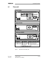
4.1.1
Indicators and keys
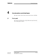
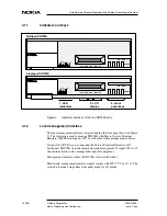
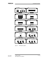
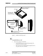
Figure 4.
Indicators and keys of the two DNT2Mi units
4.1.2
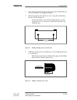
Local management interface
The local management interface is located behind the front panel door (see Figure
5). The interface is used to manage DNT2Mi with Macro Service Terminal
Emulator (MSTE) running on a PC or with other Nokia management software.
If signal 108 (DTR) is on, connecting the Service Terminal Emulator will
disconnect DNT2Mi from the remote network management. If signal 108 is off,
the entire network can be managed through this equipment.
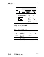
Management interface cables of DNT2Mi are listed in Table 1.
Electrically, management interface signals comply with ITU-T V.28 or V.11. The
selection is made using either front panel menus or Q1 menus.
OK
EXIT
DTR DSR DCD
RTS CTS
STATUS
PWR
TEST
P1
P2
P3
1. LED
indicators
2. LCD
display
3. Front
panel keys
Multiport DNT2Mi
Single-port DNT2Mi
OK
EXIT
DTR DSR DCD
RTS CTS
STATUS
PWR
TEST
PORT
DNT2Mi
DNT2Mi


