background image

NOGUEIRA Ind. Com. Impl. Máquinas Agrícolas S.A.

St./R: Fernando de Souza, 533 - Distrito Industrial - CEP 13877-775
Tel/Phone.: (19) 3638.1500 - Fax: (19) 3638.1556
[email protected] - www.nogueira.com.br
CNPJ: 08.510.974/0001-27

Revisão 1

4071016

Summary of Contents for SDN-170A

Page 1: ...Disc Mower Segadora de Discos SDN 170A Instructions Manual Manual de Instrucciones ...

Page 2: ......

Page 3: ...this manual This information is extremely important to identify your machine in cases when you need technical support or replacement parts Nogueira S A is always at your disposal to answer any questions or doubts and supply efficient and permanent technical support The images displayed in this manual are only for illustrative purposes Thus to facilitate your viewing the images show cutaway or the ...

Page 4: ...ing the mower 05 Environmental conservation 06 Safety 06 Safety adhesive labels 09 Application 11 Actuation 11 Coupling to the tractor 11 Preparing the driveshaft 12 Lifting the cutting bar 13 Transport and operating positions 14 Cutting height 15 Cutting marker 15 Protective covering tarp 16 Initial operation 16 Cutting 16 Maintenance 17 Safety device 17 Tightening the belts 18 Blades 18 Lubricat...

Page 5: ...5 SDN 170A Introducing the mower E n g l i s h ...

Page 6: ...expected accidents while operating it We have developed safety shielding and eliminated dangerous situations Remember keeping people healthy and their physical integrity must always be considered to the upmost We have prepared this manual to make your familiar with your mower and so that you can use it correctly and safely We recommend carefully reading it before operating the machine the first ti...

Page 7: ...r supply area Pay special attention to any children nearby Dress appropriately for operating the machine Keep long hair tied up and do not wear loose fitting clothing Remove rings chains and any other objects which can become stuck in the moving parts or mechanisms Wear personal protective equipment PPE while operating the machine Exposure to noise for prolonged period can cause hearing damage or ...

Page 8: ...p the motor disconnect it from the power take off engage the parking brake and remove the key from the ignition before getting out Leakage of the fluid from the hydraulic system is almost imperceptible Use a piece of wood or cardboard but never your hands to check for leakage Protect your hands and body as these fluids may be released at high pressure and cause serious injuries In case of any acci...

Page 9: ...9 SDN 170A Safety adhesive labels E n g l i s h ...

Page 10: ...10 Instructions Manual Safety adhesive labels ...

Page 11: ...actor so that the power take off and the SDN 170Aactuation axle of the are aligned Adjust the height of the tractor hydraulic arms so that they are the same height as the SDN 170 connecting pins First connect the left arm of the hydraulic system and next the right arm and finally the upper arm 3rd point latching them using the cotter pins After coupling the machine lift the machine remove the cott...

Page 12: ...ng different tractor models If this is necessary connect the machine to the tractor properly and the power take off must be disconnected then proceed as follows Separate the two parts of the driveshaft Connect the tubular part female to the mower axle and the solid part male to the tractor power take off Place the two parts male and female side by side Check if there is any play at least 25 mm on ...

Page 13: ...l and prepare the driveshaft and the first operation of the machine The SDN 170A is equipped with a hydraulic piston for placing the cutting bar in a vertical position appropriate for transporting the machine connected to the tractor The tractor must be equipped with a remote controller valve to operate this by a single action Connect the hydraulic hose to the tractor value Before activating the h...

Page 14: ...sition vertical Then assemble the SAFETY LATCH on piston B and place the cotter pin C fig 11 The SAFETY LATCH prevents the bar from lowering in cases of eventual failure in the hydraulic system It is extremely important in order to avoid accidents WORK POSITION Remove cotter pin C and release the SAFETY LATCH from piston B fig 11 Activate the remote controller valve on the tractor and lower the ba...

Page 15: ...he tractor and lower the mower until the connecting pins are 40 to 45 cm above the ground fig 13 SHORTENINGTHEARM FOR CUTTING LOWER LENGTHENINGTHEARM FOR CUTTING HIGHER As the mower performs it cutting work the marker forms a small furrow to show the area which has already been cut Spring A on the marker can be adjusted for increased or decreased tension based on the conditions of the product bein...

Page 16: ...ly increase the acceleration until reaching 540 RPM Observe the corresponding reading of 540 RPM for the power take off on the tractor dashboard Most tractors run at between 1700 to 2100 RPM on the tachometer The recommended tractor speed is from 7 to12 km hour When cutting the sides of the planted crop area reduce the speed due to the possible hitting of obstacles or uneven terrain curved levels ...

Page 17: ...to keep the necessary compression on the spring in the device Measure M 150 millimeters fig 18 Maintenance Safety devices Disconnect the power take off and remove the key from the tractor ignition before performing adjustments lubrication or maintenance on the machine Wait until all the parts are motionless before touching any part of the machine Keep the maintenance area clean Wet or oily floors ...

Page 18: ...ing hours It is common for new belts to become looser when first being operated The blades in SDN 170Aare reversible Change sides when you observe accentuated wear CHANGINGTHE BLADE When the cutting bar is in the normal operating position place a wooden shim or something similar between the discs to prevent their movement Remove the blade fastening screw fig 20 Change the cutting side of the blade...

Page 19: ...verify to make sure the fastening screws are well tightened Routine lubrication is the bets guarantee of good operation and durability in equipment It also helps to reduce maintenance costs The recommended interval depends on the utilization in normal operating conditions We recommend performing periodic inspections and using clean and good quality lubricants Lubrication fig 21 E n g l i s h ...

Page 20: ...ing wooded shims Hot oil Wait for about 5 minutes Cold oil Wait for about 15 minutes Remove oil plugA Place the dipstick at the same place as the bottom of the bar NOTE The dipstick is supplied with the machine fastened to the belt shielding cover fig 24 The oil level must be between the MIN and MAX markings on the dipstick fig 26 If the oil level is low fill it with SAE 90 oil till the maximum le...

Page 21: ...manual Place a tray for draining the oil under the bar fig 27 Remove the oil plugA fig 25 Remove plug B and let the oil drain out completely fig 28 Replace plug B Fill the oil in the plugAhole fig 25 with SAE 90 oil WARNING The MAX and MIN markings on the oil dipstick must not be exceeded Correct oil level will guarantee a long operating lifetime to the components An excess or lack of oil can caus...

Page 22: ...he oil for the first time after the first 10 hours of operation Other changes once a year Oil change capacity 500 ml Changing the oil Place the cutting bar in the operating position horizontal Remove the cover C and let the oil drain out completely Lower the cutting bar operating position and remove the cover D Pour the SAE 90 oil through the hole until reaching the border of the hole Replace cove...

Page 23: ...ittings in order to avoid contamination of the grease and replace them when they are damaged Lubricate grease points A and B using a grease gun after every 10 hours of operation Use special grease for bearings based on lithium soap classified as NLGI 2 EP fig 30 E n g l i s h ...

Page 24: ... a dry and protected place Conservation tips Practical guide SYMPTONS PROBABLE CAUSE SOLUTION Improper cutting Incorrect rotation Correct rotation 540 rpm in the power take off Blades are dull or damaged Sharpen change position or replace Belt slippage Tighten the belts Blades are assembled in the wrong rotation direction Verify the blade rotation direction Cutting is too high Adjust the cutting h...

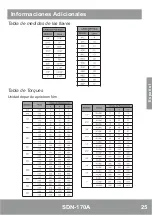
Page 25: ...25 SDN 170A Key gauge table Torque table N mTorque unit Additional information E n g l i s h ...

Page 26: ...26 Instructions Manual The SDN 170A is identified by a serial number engraved on a plate 1 located on the machine housing Write the serial number of your machine here 1 Technical Support ...

Page 27: ......

Page 28: ......

Page 29: ...icación Anote este número en el certificado de garantía contenido en este manual Esta información será muy importante para la identificación de su máquina en caso de asistencia o reposición de piezas Nogueira S A estará siempre a su disposición para responder a cualquier consulta ofreciéndole asistencia técnica eficaz y permanente Las imágenes presentadas en este manual son de carácter meramente i...

Page 30: ...ucción 03 Conociendo la segadora 05 Medio ambiente 06 Seguridad 06 Adhesivos de seguridad 09 Aplicación 11 Accionamiento 11 Acoplamiento al tractor 11 Preparación del cardán 12 Levantamiento de la barra de corte 13 Posiciones de transporte y trabajo 14 Altura de corte 15 Demarcador de corte 15 Lona protectora 16 Inicio de operación 16 Corte 16 Mantenimiento 17 Dispositivo de seguridad 17 Tensionam...

Page 31: ...egadora DEMARCADOR DE CORTE LONA PROTECTORA BARRA DE CORTE MANGUERA DEL HIDRÁULICO BUJES DE ACOPLE AL TRACTOR CARDÁN DISPOSITIVO DE SEGURIDAD TRABA DEL PISTÓN PISTÓN HIDRÁULICO CUERDA DE LA TRABA DE LA ARTICULACIÓN E s p a ñ o l ...

Page 32: ...ollamos protecciones de seguridad y eliminamos situaciones de riesgo Recordamos que la preservación de la salud y de la integridad física de las personas debe venir siempre en primer lugar Preparamos este manual para que usted conozca su segadora y así pueda utilizarlo de la manera más correcta y segura Recomendamos que lo leia atentamente antes de utilizar la máquina por primera vez Si surge cual...

Page 33: ...os niños Vístase apropiadamente para operar la máquina Prenda el cabello largo y no use ropa demasiado holgada Sáquese anillos cadenas y demás elementos que puedan prenderse en las piezas o mecanismos en movimiento Use equipo de protección individual EPI al operar la máquina La exposición prolongada al ruido puede causar daño o pérdida de la audición Use protectores auriculares y gafas de segurida...

Page 34: ...e en viaductos Nunca abandone el tractor con la máquina funcionando Pare el motor desconecte el toma de fuerza accione el freno de estacionamiento y retire la llave del contacto antes de abandonarlo El escape de líquido del sistema hidráulico puede ser casi imperceptible Utilice madera o cartón y nunca las manos al buscar pérdidas Proteja las manos y el cuerpo fluidos la alta presión pueden causar...

Page 35: ...dos por los discos Apague el tractor y retire la llave del arranque antes de realizar servicios de mantenimiento regulado lubricació limpieza etc en la máquina De esta forma usted impedirá el accionamiento accidental y evitará situaciones de peligro con riesgo de accidentes graves No se acerque a la máquina antes de su paralización completa Recuerde que las partes rotativas no paran inmediatamente...

Page 36: ...na podrá causar lesiones graves Nunca intente localizar una pérdida de fluido con las manos Utilice un pedazo de cartón o madera La penetración de fluido en la piel puede causar infecciones y gangrena Número de giros por minuto y sentido de rotación en el toma de fuerza Al operar la máquina use equipo de protección individual EPI La exposición prolongada al ruido sin protección puede provocar pérd...

Page 37: ...de fuerza y el eje de accionamiento de la SDN 170A queden alineados Regular la altura de los brazos del hidráulico del tractor en la misma altura de los bujes de acople de la SDN 170A Acoplar primero el brazo izquierdo del hidráulico a continuación el brazo derecho y por último el brazo superior 3o punto trabándolos con los contrabujes Después del acoplamiento levante la máquina retire el contrabu...

Page 38: ...s de tractores Si fuere necesario con la máquina debidamente acoplada al tractor y el toma de fuerza desconectado proceder de la siguiente manera Desencajar las dos partes del cardán Acoplar la parte tubular hembra en el eje de la segadora y la parte maciza macho en el toma de fuerza del tractor Colocar las dos partes macho y hembra una al lado de la otra Observe si hay una holgura de como mínimo ...

Page 39: ...onamiento de la máquina La SDN 170A está equipada con un pistón hidráulico para colocación de la barra de corte en la posición vertical apropiada para el transporte de la máquina acoplada al tractor Para su funcionamiento el tractor debe estar equipado con una válvula de comando remoto de simple acción Acoplar la manguera hidráulica a la válvula del tractor Antes de accionar el pistón hidráulico l...

Page 40: ...DE SEGURIDAD impide que la barra descienda en el caso de una eventual falla en el sistema hidráulico Su utilización es de extrema importancia para evitar que acontezcan accidentes POSICIÓN DE TRABAJO Retire el contrabuje C y suelte la TRABA DE SEGURIDAD del pistón B fig 11 Accione la válvula del comando remoto del tractor y baje la barra hasta la posición de trabajo horizontal fig 09 fig 10 fig 11...

Page 41: ...el tractor y baje la segadora hasta que los bujes de acople estén de 40 a 45 cm sobre el suelo fig 13 ACORTAR ELBRAZO CORTAMÁS BAJO ALONGAR ELBRAZO CORTAMÁSALTO Amedida que la segadora realiza el trabajo el demarcador forma un pequeño surco cuya finalidad es facilitar la visualización del área que ya fue cortada El espieral A del demarcador puede ser regulado para mayor o menor tensión de acuerdo ...

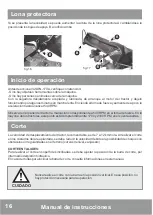
Page 42: ... RPM en el toma de fuerza En la mayoría de los tractores este punto está comprendido entre 1700 y 2100 RPM en el cuentavueltas La velocidad de desplazamiento del tractor recomendable es de 7 a 12 km hora Al realizar el corte en los costados del área plantada se debe reducir la velocidad debido a la posibilidad de choque con obstáculos o irregularidades en el terreno curvas de nivel zanjas etc CORT...

Page 43: ...esión necesaria Medida M 150 milímetros fig 18 Mantenimiento Dispositivo de seguridad Desconecte el toma de fuerza y retire la llave del arranque del tractor antes de realizar regulados ajustes lubricación o mantenimiento en la máquina Aguarde hasta que todos los componentes estén sin movimiento antes de tocar cualquier parte de la máquina Mantenga el área de mantenimiento limpia Pisos mojados o g...

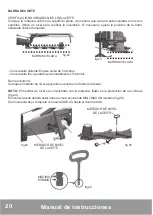
Page 44: ...riodo es común el aflojamiento de correas nuevas Las cuchillas de la SDN 170A son reversibles Cambie el lado de uso al observar desgaste acentuado CAMBIADE LACUCHILLA Con la barra de corte en la posición normal de trabajo coloque un calce de madera o algo similar entre los discos para evitar que los mismos giren Retire el tornillo de fijación de la cuchilla fig 20 Cambie el lado de uso de la cuchi...

Page 45: ...SCOS SENTIDO DE CORTE DE LAS CUCHILLAS CUIDADO CUIDADO Verifique diariamente el ajuste de todos los tornillos de fijación de los discos de corte Observe el estado de las cuchillas y tornillos La holgura excesiva entre el tornillo y el orificio de la cuchilla puede causar situaciones peligrosas Substitúyalos cuando presentaren desgaste Utilice solamente tornillos y cuchillas originales Nogueira Baj...

Page 46: ...inutos Con el aceite frío Aguarde aproximadamente 15 minutos Retire el bulónA Coloque el medidor de nivel apoyando su punta en el fondo de la barra NOTA El medidor de nivel es suministrado con la máquina fijado en la protección de las correas fig 24 El nivel del aceite deberá estar entre las marcaciones de MIN y MAX del medidor fig 26 Si el nivel está bajo complete con aceite SAE 90 hasta el nivel...

Page 47: ...ente para la recolección del aceite bajo la barra Retire el bulónA fig 25 Retire el bulón B y deje escurrir totalmente el aceite fig 28 Recoloque el bulón B Abastezca por el bulónA fig 25 con aceite SAE 90 ATENCIÓN Los indicadores MAX y MIN del nivel de aceite de la barra no deben ser excedidos El nivel correcto del aceite irá a garantizar una larga vida útil a los componentes El exceso o la falta...

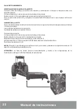
Page 48: ...n después de las primeras 10 horas de trabajo Los cambios siguientes una vez al año Cantidad de aceite en el cambio 500 ml Para cambiar el aceite Coloque la barra de corte en la posición de trabajo horizontal Retire el tapón C y deje escurrir completamente el aceite Baje la barra de corte posición de trabajo y retire el tapón D Através del orificio C coloque aceite SAE 90 hasta alcanzar el borde d...

Page 49: ...ajo Utilizar grasa especial para rodamientos a base de jabón de litio clasificación NLGI 2 EP fig 30 Características técnicas Ancho de trabajo 1 65 m Ancho de transporte 1 90 m Peso 415 kg Potencia requerida toma de fuerza a partir de 35 cv Rotación en el toma de fuerza 540 RPM Sistema de acople al tractor categorías I e II Cantidad de discos 04 Cantidade de cuchillas 12 Cantidad de correas 03 Inc...

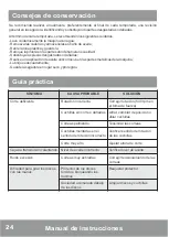
Page 50: ...uarde la segadora en lugar seco y protegido Consejos de conservación Guía práctica SÍNTOMA CAUSA PROBABLE SOLUCIÓN Corte deficiente Rotación incorrecta Corregir rotación 540 rpm en el toma de fuerza Cuchillas sin corte o dañadas Afilar cambiar de posición o afilar cuchillas Correas patinando Tensionar las correas Cuchillas montadas en el sentido de rotación incorrecto Verificar sentido de rotación...

Page 51: ...25 SDN 170A Informaciones Adicionales Tabla de medidas de las llaves Tabla de Torques Unidad de par de apriete en N m E s p a ñ o l ...

Page 52: ...nicaciones o requerir auxilio de la asistencia técnica Nogueira siempre informe el número de serie y el modelo de la máquina presentes en la plaqueta de identificación Al substituir piezas utilice siempre artículos orinales Nogueira Solamente las piezas originales son fabricadas de acuerdo con los diseños materiales y especificaciones de proyecto pasando por un estricto estándar de calidad 1 Asist...

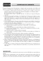
Page 53: ...iones realizadas por personas no auto rizadas por el fabricante 4 4 Empleo de piezas o componentes no originales 4 5 Uso de tractor con potencia superior a la máxima recomendada en el Manual de Instrucciones 4 6 Presentación de Notas Fiscales de compra rasuradas o adulteradas 5 Las reclamaciones sobre eventuales defectos durante el período de la garantía deberán ser presentadas a los revendedores ...

Page 54: ...ara toda su línea de máquinas Para mayor información consulte el sitio www nogueira com br o póngase en contacto con el Servicio de Atención al Cliente a través del teléfono 55 19 3813 9226 TÉRMINO DE RECIBO INSTRUCCIONES PARA EL REGISTRO EN EL SITIO 1 Llene el TÉRMINO DE RECIBO con la información solicitada y firme 2 Dispare el TÉRMINO DE RECIBO completado y la factura de venta 3 Acceder al sitio...

Page 55: ......

Page 56: ...m Impl Máquinas Agrícolas S A St R Fernando de Souza 533 Distrito Industrial CEP 13877 775 Tel Phone 19 3638 1500 Fax 19 3638 1556 nogueira nogueira com br www nogueira com br CNPJ 08 510 974 0001 27 Revisão 1 4071016 ...

Reviews: