TPC6000
‐
A152
User
Manual
18
2.3
Hard
drive
installation
This
section
outlines
the
installation
of
the
hard
drive
in
the
TPC6000
‐
A152
‐
T.
To
install
the
hard
drive,
please
follow
the
steps
below:
Step
1:
Flip
over
this
device
and
you
can
see
its
back.
Step
2:
Unfasten
the
4
silver
retention
screws
on
the
left
and
right
side.
(Figure
2
‐
1)
Step
3:
Lift
the
cover
to
remove.
Step
4:
Locate
the
HDD
bracket.
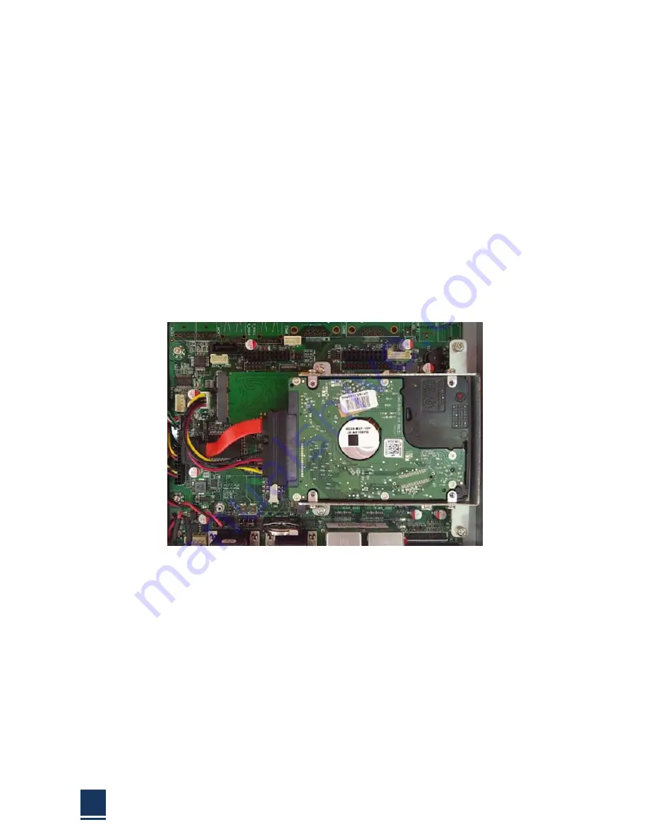
Step
5:
Insert
the
SATA
connector
at
the
end
of
the
HDD
into
the
bracket
to
connect
the
motherboard
SATA
connector
to
the
hard
drive
SATA
connector
as
shown
in
the
figure
below.
Step
6:
Plant
the
screw
on
the
HDD
bracket.
Step
7:
Replace
the
covers
and
screws.
2.4
SSD
installation
by
using
mSATA
The
installation
for
a
SSD
is
described
in
this
section.
Step
1:
Remove
the
HDD
bracket
just
like
mentioned
on
the
“Hard
drive
installation
steps”.
Step
2:
Insert
the
mSATA
SSD
into
the
mSATA
slot
as
shown
in
the
Figure
2
‐
4
below:
Summary of Contents for TPC6000-A152
Page 1: ...TPC6000 A152 User Manual 1 User Manual Ver1 0 TPC6000 A152 Industrial Panel PC...
Page 8: ...TPC6000 A152 User Manual 8 Chapter 1 OVERVIEW...
Page 14: ...TPC6000 A152 User Manual 14 1 6 Dimensions Figure 1 5 TPC6000 A152 T dimensions...
Page 15: ...TPC6000 A152 User Manual 15 Chapter 2 INSTALLATIONS...
Page 35: ...TPC6000 A152 User Manual 35 Press NEXT to continue...
Page 40: ...TPC6000 A152 User Manual 40 Press YES to agree the License agreement then go to the next step...
Page 42: ...TPC6000 A152 User Manual 42 Press YES to continue...
Page 45: ...TPC6000 A152 User Manual 45 Press NEXT to continue...
Page 47: ...TPC6000 A152 User Manual 47...
Page 50: ...TPC6000 A152 User Manual 50 Press NEXT to continue Press INSTALL to continue...
Page 56: ...TPC6000 A152 User Manual 56 Chapter 3 BIOS Setup...
Page 61: ...TPC6000 A152 User Manual 61 Figure 3 3 1 PCI Subsystem Configuration Setting...
Page 62: ...TPC6000 A152 User Manual 62 3 3 2 ACPI Setting Figure 3 3 2 ACPI Configuration Setting...
Page 65: ...TPC6000 A152 User Manual 65 3 3 5 USB Configuration Figure 3 3 5 USB Configuration...
Page 67: ...TPC6000 A152 User Manual 67 3 3 7 PC Health Status Figure 3 3 7 PC Health status...
Page 68: ...TPC6000 A152 User Manual 68 3 3 8 PPM Configuration Figure 3 3 8 PPM Configuration...
Page 69: ...TPC6000 A152 User Manual 69 3 4 Chipset Settings host bridge Figure 3 4 Chipset Settings...
Page 70: ...TPC6000 A152 User Manual 70 3 4 1 Intel graphic configuration...
Page 72: ...TPC6000 A152 User Manual 72 3 5 Chipset settings south bridge Figure 3 5 Chipset Settings...
Page 74: ...TPC6000 A152 User Manual 74 3 5 2 Power on configuration Figure 3 5 3 Power on Settings...
Page 76: ...TPC6000 A152 User Manual 76 Figure 3 5 3 Boot configuration...
Page 77: ...TPC6000 A152 User Manual 77 3 6 Security settings Figure 3 6 Security settings...
Page 80: ...TPC6000 A152 User Manual 80 Chapter 4 System Maintenance...
Page 82: ...TPC6000 A152 User Manual 82 A Safety Precautions...
Page 86: ...TPC6000 A152 User Manual 86 B ALC662 Digital Microphone Configuration...
Page 90: ...TPC6000 A152 User Manual 90 C Watchdog Timer...
Page 93: ...TPC6000 A152 User Manual 93 D Hazardous Materials Disclosure...
Page 96: ...TPC6000 A152 User Manual 96 Chapter 5 Appendix A...


