

6
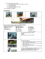
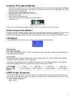
Install the VFD (optional) Module
o
First, perform a quality check, turn off your system (after build), hold the module, and simply plug the USB cable
to the onboard USB port, and turn on your system, your initial screen will show up with USB power. Then, follow
the below steps to install the VFD.
o
Take out the 4 screws that hold the front panel
o
Remove the black blocking filter on the VFD window
o
Install the VFD module
o
Secure the panel back to the case
o
Connect the USB cable to the module and onboard USB port
o
Install Driver CD
Note: If you are installing the VFD after the system is built, some cables may need to be re-routed.
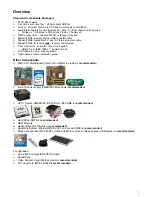
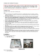
Other Component Installation
For other components, including hard drive; RAM; CPU & cooler; optical drive, video card, sound card, TV tuner card and
operating system etc., plan the installation steps carefully, and follow the user manual and motherboard manual
instruction to avoid damages. Always install the power supply at last to make more space during the installation process.
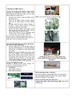
LCD Module
LCD will display the CPU & Case Temp. reading / CPU Cooler Fan Speed reading
Alarm Features
CPU Alarm Temperature
When CPU temperature hits 65ºC or 149F, the temperature reading will flash constantly until the temperature
drops below the alarm degree.
CPU Fan Alarm
When the fan stops running for whatever reason during working mode, the CPU fan speed reading will flash
constantly in “0000” until the fan is re-spinning again.
LCD shows CPU temperature and CPU heatsink fan speed when connecting appropriately. The fan speed is
automatically adjusted by the CPU temperature. See below chart for more details.
CPU Temp
Æ
0-86 F
86 F & up
104 F & up
122 F & up
CPU Fan Spin
Speed
70% of full speed
80% of full speed
90% of full speed
100% full speed
S/PDIF Output Connection
It is a standard S/PDIF output jack. Connect the header to the onboard S/PDIF output port, and connect the jack to your
receiver via a coaxial digital cable. (remember to change your Audio setting to pure digital output) See below color codes
when connecting the cable to the board:
o
White – “Data” or “S/PDIF out”
o
Black
–
Ground