NKK SWITCHES IS-S04G1LC-S User Manual Download Page 3


IS-S04G1LC-S User Manual


IS-S04G1LC User Manual C                                    Page 3 of 13 

www.nkkswitches.com 

• 

[email protected]


1120 

1. LCD 64x32 SmartDisplay Switch 

 
The LCD 64x32 SmartDisplay switch is a graphic 64x32 pixels LCD display mounted in the key cap of 
a tactile momentary pushbutton. It has an RGB backlight with 64 color options and 8 brightness level. 
 

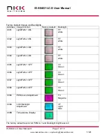
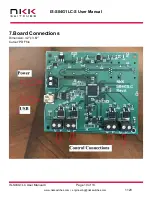
The picture below is available backlight colors of LCD64x32. The top 2 digits on each color are the code for back light color. 


Backlight Color Code Table 
 

SmartDisplay is ideal for use in applications with multiple, complex functions which would ordinarily 
require many dedicated switches and complex training. The dynamic nature of the system allows for 
instantaneous transitions from generalized lists of categories down to function specific actions. This 
reduces the need for complicated controls and shortens the time for training by only displaying 
relevant options and commands. 
Backlight colors can be used to easily recognizable functions scheme.  
 
NKK can supply subsystems with any number and configuration of LCD 64x32 switches. The 
subsystem can have communications such as USB, Ethernet, CAN, RS232, RS485 etc. The 
subsystem additionally can sense/control various status, gauges, and devices. 
 
 
To help with development, NKK offer engineering kits with schematic and source code for all the 
SmartDisplay’s. A free software, Engineering Kits Communicator, is available to test and download 
images for communication to various controllers. Also, NKK Switches provides all the documentation 
necessary to get up and running quickly on our website: 

https://www.nkkswitches.com/SmartDisplay-

resources/


Please contact 

[email protected]

 with your requirements or any question. 


Summary of Contents for IS-S04G1LC-S

Page 1: ...S04G1LC S User Manual Revision C All Rights Reserved Worldwide NKK Switches makes no warranty for the use of these products and assumes no responsibility for any errors which may appear in this docum...

Page 2: ...om 1120 Table of Contents 1 LCD 64x32 SmartDisplay Switch 3 2 General IS S04G1LC S Features 4 3 Electrical Specifications 5 4 Images and Backlights 6 5 Operational Overview 8 6 Saving Images Using Eng...

Page 3: ...ories down to function specific actions This reduces the need for complicated controls and shortens the time for training by only displaying relevant options and commands Backlight colors can be used...

Page 4: ...switches toggle between ON OFF corresponding control Eight level PWM control for each light or fan Holding any of the switches down for about 2 5 second allow for changing the PWM level Pressing the s...

Page 5: ...ent 100 mA to 250 mA Depends on Backlight brightness and colors Does not include lights fans current consumption PWM period 459 microseconds PWM duties Level Duty cycle 1 1 36 2 2 36 3 3 36 4 8 36 5 1...

Page 6: ...communicator images must be saved in the proper format LCD 64x32 Monochrome bitmap bmp 64x24 pixels There are 11 images associated with the light fan control system next page The Backlights can be mod...

Page 7: ...Light FAN 1 ON FF white 0002 Light FAN 2 ON FF white 0003 Light FAN 3 ON FF white 0004 Light FAN 4 ON FF white 0005 Light FAN 1 OFF 33 Green 0006 Light FAN 2 OFF 33 Green 0007 Light FAN 3 OFF 33 Green...

Page 8: ...at the same time switch 1 display image of address 10 and the backlight brightness level Releasing and pressing the switch 1 will cycle through the 8 brightness levels When the switch is released for...

Page 9: ...drop down menu at the top select the COM port of the system usually the last one 3 Click the Open Port button 4 Press the call button and verify the system responds with 61 in blue text in the left te...

Page 10: ...IS S04G1LC S User Manual IS S04G1LC User Manual C Page 10 of 13 www nkkswitches com engineering nkkswitches com 1120 7 Board Connections Dimension 3 2 x 3 67 Cutout PDF file...

Page 11: ...Therefore all data received will be in the 0x30 0x46 number range and anything received outside that is invalid For example Data to be sent is 0x3D Each nibble is assigned its own byte 0x3 and 0xD Ea...

Page 12: ...bbles ASCII A byte value representing a symbol Communication There are two formats to transmit a byte Format 1 Hex format A hex byte is transmitted without any change to it xxH will be used to denote...

Page 13: ...hes disclaims any liability or warranty obligation with respect to any product that is misused damaged by any user or not used in conformity with all applicable product specifications NKK SWITCHES HER...

Reviews: