12
[email protected]
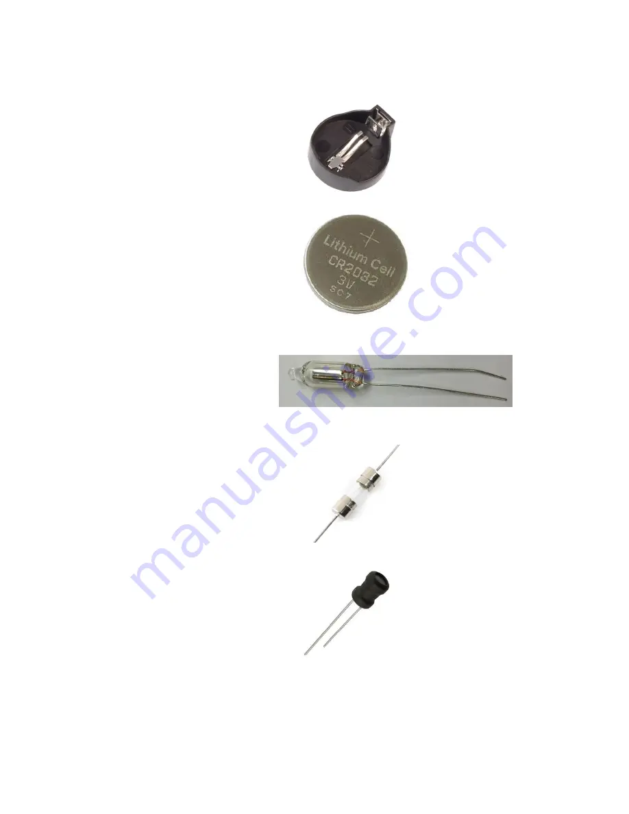
Miscellaneous
CR2032 Battery socket (BAT_1)
Battery
Neon bulb (DB1, DB2)
Fuse
330uH, 1A Inductor (L1)
Page 1: ...d user manual Bring to your home a piece of history with The Vintage Nixie Clock and its Cold War era components The clock will give a cosiness and a uniqueness for your house To warm clock digits shi...
Page 2: ...24 hour operation modes Time accuracy is provided by built in RTC Real Time Clock based on extremely precise DS3231 module with temperature compensation and backup with CR2032 battery Programmable le...
Page 3: ...g placement and orientation prior to soldering will save hours of mistakes search and rework later REMEMBER A properly placed components and carefully soldered PC board will perform well for years a h...
Page 4: ...r adapter in your local electronics shop because it will be equipped by necessary grid plug You may have similar power adapter in your house also because such type power adapters are popular and widel...
Page 5: ...ion RESISTORS R1 1k 0 25W R2 470k 0 25W R3 3 6k 0 25W R4 0 5 0 5W R5 R6 R7 R8 R9 R10 R11 R15 R19 R20 10k 0 25W R12 330 0 25W R16 R17 270k 0 25W CAPACITORS C1 2 2uF 250V Electrolytic C2 C3 C5 C6 0 1uF...
Page 6: ...805 U2 MC34063 U3 K155ID1 U4 ATMEGA328P PU U5 DS3231 MISCELLANEOUS PCB Nixie Clock PCB BAT_1 CR2032 Battery socket Battery 3V CR2032 DB1 DB2 Neon bulb FUSE 0 5A L1 330uH 1A Inductor N1 N6 IN 14 Nixie...
Page 7: ...first second and third coloured bands on the resistors indicate the resistance using a colour code This table indicates how to convert each colour to its numerical equivalent Gold band means 5 toleran...
Page 8: ...ction the bands should be read Therefore we recommend that the resistors will be identified with a multimeter Use the resistor code to identify and sort all of the resistors One good way to keep them...
Page 9: ...9 nixiediy gmail com Transistors BC547 Q5 Q6 BC557 Q1 MPSA42 Q7 IRF840 MOSFET Q2 EL817 OK1 OK6...
Page 10: ...10 nixiediy gmail com Diodes 1N4004 D1 UF4004 D3 1N914 D2 LED 3mm LED1 LED6...
Page 11: ...11 nixiediy gmail com Integrated Circuits LM7805 U1 MC34063 U2 K155 1 U3 ATMEGA328P PU U4 DS3231 U5...
Page 12: ...12 nixiediy gmail com Miscellaneous CR2032 Battery socket BAT_1 Battery Neon bulb DB1 DB2 Fuse 330uH 1A Inductor L1...
Page 13: ...13 nixiediy gmail com Button S1 S3 16 pin socket 28 pin socket Power socket 5 5mm x 2 1mm Speaker PCB Spacers 3mm screw...
Page 14: ...F Ceramic 4 2 2nF Ceramic 1 TRANSISTORS BC557 1 IRF840 MOSFET 1 BC547 2 MPSA42 1 EL817 Optocoupler 6 DIODES 1N4004 1 1N914 1 UF4004 1 LED 3mm 6 INTEGRATED CIRCUITS LM7805 1 MC34063 1 K155ID1 1 ATMEGA3...
Page 15: ...high definition pictures If anywhere is uncertainty PCB view can magnify and an interested component may to view in details The side of the board that has printed component marking is the component si...
Page 16: ...and diode D1 so that they form a right angle to the component body 2 5 To install place the leads of the component through the appropriate holes and press the component down against the component side...
Page 17: ...ds slightly outward to hold the component in place Solder the leads to the contact and trim the excess lead wire above the solder joint NOTES To make sure that capacitor C7 and diode D1 polarity is no...
Page 18: ...2 2uF 250V C3 C5 0 1uF C4 2 2nF R4 0 5 0 5W R1 1k R3 3 6k R2 470k 3 1 All resistors except R4 leads bend in accordance with this picture that each resistor place on board surface will be minimal 3 2...
Page 19: ...shown below 4 3 Plug in the power supply and then test HV source operability using a multi meter in DC voltmeter mode Touch the black probe on the GND test point and the red probe on the 165 V test p...
Page 20: ...t and the red probe on the 5V test point The voltage should measure between 4 8 and 5 2 Volts If not disconnect power and check all relevant joints quality and polarity Do not continue with the assemb...
Page 21: ...notch in the socket lines up with the notch marking in rectangular outline printed on the board After inserting a socket into the board solder its two opposite corners pins first This will hold the s...
Page 22: ...its socket mounting are similar as pointed in item 5 Check your work results with picture below 6 3 One end of the OK1 OK6 symbol on the PCB has a half hole at one end of the symbol In optocouplers OK...
Page 23: ...resistor into the board holes marked as R5 R6 and R7 respectively and solder it leads 7 2 Solder capacitor C6 on the board at location C6 7 3 Battery has polarity and requires special attention when m...
Page 24: ...ht angle tactile button switches Insert them into locations S1 S2 and S3 and make sure that they sit flat on the board Solder all four pins of each switch 8 2 All resistors R8 R9 and R10 leads bend in...
Page 25: ...into the board holes marked as Q6 that its case flat edge is above the flat edge of the placement marking Solder it leads 9 3 Bend speaker leads Speaker is polarized device and requires special atten...
Page 26: ...10 3 Each LED LED1 LED6 must be mounted pointing vertically upwards for the components side of the board so that the long lead the anode is inserted into the relevant hole marked Be sure to mount LED...
Page 27: ...with item 3 1 Insert them into locations R15 R16 R17 and solder their leads as pointed on the picture 11 2 Install the transistor Q7 legs into the board holes marked as Q7 that its case flat edge is...
Page 28: ...ectly You must follow our step by step assembly instructions For clock six pcs IN 14 nixie tubes are necessary 12 1 For each tube cut wires until 15 30 mm length By using long nose pliers smooth out a...
Page 29: ...solder its two opposite leads first This will hold the tube in place Look at it carefully to check it proper height and reciprocal arrangement It is important that tubes will not inclined to the sides...
Page 30: ...30 nixiediy gmail com 12 4 To solder Neon bulbs DB1 and DB2 in place on the PCB 12 5 Cut the excess leads short as close as possible to the PC board...
Page 31: ...nstalled and soldered properly the clock shall begin to operate 13 PCB dimensions PCB dimensions pointed on the drawing below They will be necessary if you decide to make the case for clock All dimens...
Page 32: ...ither 12 or 24 mode Mode 4 Set date DD MM YY Mode 5 24 or 12 hours mode 0 Set 24 hour mode 1 Set 12 hour mode 12 hour mode AM PM indication displayed on neon colon indicators AM neon indicators not bl...
Page 33: ...nixiediy gmail com 15 Contact information Please use the address below for all correspondence and returns Address Edvin Svarabovich Kaminkelio g 26 36 Vilnius LT 02192 Lithuania Email nixiediy gmail c...