background image

Diagnosis

page 109

rev. 00 / 12.04.2017

Diagnosis

30  Basics of Diagnosis Menus

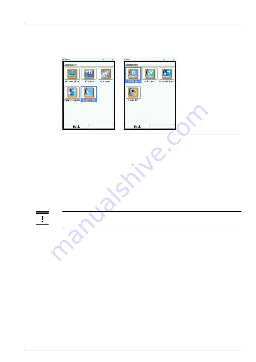
Fig. 30-1 

Diagnosis menu

The >Diagnosis< menu can be found in menu >Application< and is divided into four sub-

menus.
The Diagnosis menu and all submenus are pure read-only and simulation menus.
In this section the following settings can be verified or simulated:

•  h-Sensors (level and adjustment height)
•  v-Sensors (article no., firmware version, serial no. and velocity)
•  Inputs and outputs (status and simulation)
•  Simulation

Important Note

Always follow the safety information on simulation on page 117.

Summary of Contents for NivuFlow Mobile 550

Page 1: ...F L O W Flow Measurement Transmitter for Radar Sensors NivuFlow 550 Instruction Manual Firmware Revision 2 09 Original Manual German...

Page 2: ...pean Economic Area EEA this instruction manual must be translated into the language of the country in which the device is to be used Should the translated text be unclear the original instruction manu...

Page 3: ...Instruction manual NivuFlow 550 page 4 rev 00 12 04 2017 Modifications Rev Modifications Person in charge Date 00 First version MoG 12 04 2017...

Page 4: ...nnections and user elements 12 2 1 Power supply 12 2 2 NivuFlow control elements 13 2 3 Tasks of control elements 13 2 4 Interfaces 14 SAFETY INSTRUCTIONS 15 3 In general Used symbols and signal words...

Page 5: ...port 25 11 6 Return 25 11 7 Installation of spare parts and parts subject to wear and tear 25 FUNCTIONAL PRINCIPLE 26 12 Operating Range 26 13 Functional Principles 26 13 1 Flow Velocity Measurement 2...

Page 6: ...on 33 17 2 Sensor Connection at NivuFlow 34 17 3 Overvoltage Protection 36 18 Transmitter Connection 39 18 1 Connection to the Terminal Blocks 39 18 1 1 Connection Diagrams 40 18 2 Switching on voltag...

Page 7: ...Sludge Level 59 23 1 4 Flow Velocity Evaluation 59 23 1 5 Low Flow Suppression 60 23 1 6 Damping 61 23 1 7 Stability 61 23 2 Setting Parameters in h Sensors Menu 61 23 2 1 h Sensor Types 61 23 2 2 De...

Page 8: ...rvice 94 25 5 1 Change System Password 95 25 5 2 Restart 95 25 5 3 Measurement Restart 95 25 5 4 Parameter Reset 96 26 Communication Parameters Menu 96 27 Display Parameters Menu 98 28 Connections 100...

Page 9: ...f Diagnosis Menus 109 31 Diagnosis h Sensors 110 32 Diagnosis v Sensors 111 33 Inputs and Outputs Analog and Digital 112 33 1 Analog Inputs 112 33 2 Analog Outputs 113 33 3 Digital Inputs 115 33 4 Dig...

Page 10: ...mage to persons or material due to incorrectly understood information in this instruction In case of selling the instrument this instruction manual shall be provided to the purchaser since it is a par...

Page 11: ...black RD red TR transparent BU blue WH white GNYE green yellow GN green YE yellow BN brown GY grey PK pink 2 Connections and user elements 2 1 Power supply The connection for power supply is located...

Page 12: ...unction key Fig 2 2 Control elements 2 3 Tasks of control elements Colour display You can read all settings when parameter setting and in diagnostics Left function key Initially this key takes you to...

Page 13: ...g outputs AO Selection of digital inputs DI Selection of digital outputs DO Menu data Selection of trend and day totals F F You will find a description on how to use the control elements in chapter 20...

Page 14: ...ndicates a possible danger with medium risk which may result in a life threatening situation or severe bodily injury if it is not avoided CAUTION Warnings in low risk or property damages Indicates a p...

Page 15: ...rally and at any time These notes and warnings will not be repeated for each description within the document WARNING Germ contamination Please note that due to the operation in the waste water field t...

Page 16: ...The manufacturer is not responsible for failures resulting from improper use 6 Use in accordance with the requirements Note The instrument is intended solely for the purpose described below Modifying...

Page 17: ...cord ing EC type examination certificate 7 User s Responsibilities Important Note In the EEA European Economic Area national implementation of the frame work directive 89 391 EEC and corresponding ind...

Page 18: ...tes on the product itself are per sons who are sufficiently familiar with installation mounting starting up and operation of the product and who have the relevant qualifications for their work for exa...

Page 19: ...Interfaces 3 Graphic display 4 Control Elements 5 DIN rail fastening X1 Power supply air ultrasonic sensor connection via RS485 Interfaces LAN and Bus X2 Digital in outputs 1x RS485 and analog in out...

Page 20: ...te is fixed on the side of the enclosure and contains the following Name and address of the manufacturer CE label Information on type and series serial no if available Power supply In case of enquirie...

Page 21: ...Instruction Manual NivuFlow 550 page 22 rev 00 12 04 2017 Nameplates Fig 9 4 Nameplate AC version Fig 9 5 Nameplate DC version...

Page 22: ...0x360 pixel 65536 colours Programming Dialog mode using rotary pushbutton and two function keys in German English and French Connection Plug with spring cage terminal clamps Inputs 1x 4 20 mA for exte...

Page 23: ...sure type ZUB0 NFW0 Power supply A0 100 240 V AC D0 10 35 V DC Firmware extensions 0 none Number of measurement places 1 1 measurement place 11 2 Delivery The standard delivery of the NivuFlow 550 con...

Page 24: ...customer cost to NIVUS GmbH in Eppingen using the original packaging Insufficiently franked shipments will not be accepted 11 7 Installation of spare parts and parts subject to wear and tear We herew...

Page 25: ...hits the waves on the water surface is reflected and is re detected by the sensor The reflection from the water surface causes a frequency shift The Radar sensor measures the wave movement and compute...

Page 26: ...aster can be used as well Note i Series sensors have pre programmed measurement ranges For further reference please see the i Series sensors instruction manual i Sensors can be put into operation even...

Page 27: ...mains power The sensitive electronic components inside the unit may get damaged by static electricity The manufacturer recommends the following steps to prevent the device from getting damaged due to...

Page 28: ...ical current Disconnect the unit from mains power Working on electric connections may cause the risk of electric shocks Observe electric information provided on the nameplate Non observance may result...

Page 29: ...tion to the Terminal Blocks 15 1 2 Power supply DC The DC version can be directly operated from the 24 V direct current network of a control cabinet Prerequisites input voltage available at the input...

Page 30: ...against electrical shock according to the laws and regulations For example Open the cabinet field enclosure only by the use of a tool or key or use fault current circuit breaker or similar Non observ...

Page 31: ...stallation instruction The parameters of the measurement place shall be set prior to installation Information on how to prepare the measurement place as well as the according dimensions can be taken f...

Page 32: ...pter 17 3 Overvoltage Protection Between iXT and transmitter standard cable Maximum cable lengths between transmitter and iXT if using the NIVUS standard cable LiYC11Y 2x1 5 mm 1x2x0 34 mm PA 50 metre...

Page 33: ...ignal cable is to be installed in ground concrete or similar 17 2 Sensor Connection at NivuFlow Sensor wiring diagrams can be found in the according Technical Description or Instruction Manual The con...

Page 34: ...sensor NivuBar NivuCompact 2 wire echo sounder or similar which is supplied by the NivuFlow Connect the 2 wire sensor according to Fig 17 5 Fig 17 5 h NivuFlow 16 17 HART X2 Zone 1 Connecting a 2 wir...

Page 35: ...the sensors in Ex areas consider the connected loads of the overvoltage protection devices as well as capacity and inductance of the NIVUS sensor cables OCL L1 addition ally The maximum permissible N...

Page 36: ...in 1 5 mm DataPro 2x1 12 V 12V 11mTr N 1 2 1p 2p 8 9 10 X1 11 12 RD BU min 1 5 mm SonicPro 3x1 24 V 24V 1 2 3 1p 2p 3p GN WH BK OCL L1 supply outer shield UE GND RxTx RxTx min 1 5 mm DataPro 2x1 12 V...

Page 37: ...2 ext power Sensor NivuMaster 1p 2p 1 2 DataPro 2 x 1 24 V 24 V min 1 5 mm Overvoltage protection of 4 20 mA input from external transmitter Fig 17 12 11 12 13 X2 14 15 min 1 5 mm SonicPro 3x1 24 V 24...

Page 38: ...are used To connect the power supply use a slot screwdriver with a blade width of 3 0 or 3 5 mm Important Note Unplug and connect the tension clamp terminal blocks only in de energised condition disco...

Page 39: ...ument Operate the instrument with the tension clamp terminal block screwed on only Non observance may result in personal injuries Fig 18 1 1 2 3 4 5 6 7 8 9 10 11 12 13 14 15 16 17 X1 CTS RTS RxD TxD...

Page 40: ...p terminal block is to connect the protective conductor as well as the AC power supply and is an integral part of the instrument Operate the instrument with the tension clamp terminal block screwed on...

Page 41: ...Instruction Manual NivuFlow 550 page 42 rev 00 12 04 2017 Fig 18 3 230V AC connections of power supply Fig 18 4 DC connections of power supply...

Page 42: ...hall not be put into operation before the installation has been finished and checked Follow the hints in the instruction manual to eliminate the risk of faulty or incorrect setting of parameters Befor...

Page 43: ...area 3 4 Functions 5 Name of measurement place 6 Date time 7 Error message sent or display for active service mode Fig 20 1 Display overview 20 2 Using the Control elements First select the main menu...

Page 44: ...ith YES The password query for the parameter settings appears Fig 20 3 Password query for parameter settings Enter the password default setting 2718 After accepting the new parameters the NivuFlow con...

Page 45: ...native function 3 Press the rotary pushbutton until the desired character is highlighted black By pressing the character is applied to the text box automatically 4 Repeat this process until the comple...

Page 46: ...g of parameters for the dimensions of measurement places selection of sensors and analog and digital inputs and outputs Data visually indicate charts on flow rate level and average flow velocity visua...

Page 47: ...e parameters you need to enter a valid password first Default setting 2718 21 2 Change Password F F See also chapter 25 5 1 Change System Password You can change the default password at any time Howev...

Page 48: ...serve chapter 20 Operation Basics 22 2 Functions Top Menu Level 22 2 1 Application Menu Fig 22 2 Application Menu This menu is the most extensive and most relevant when it comes to set the transmitter...

Page 49: ...aluation radar Low flow suppression Damping of signal evaluation and output Stability of signal evaluation and output 22 2 2 Data Menu Fig 22 3 Data Menu The Data menu allows accessing all measurement...

Page 50: ...on the transmitter Article No Firmware version Serial No Furthermore the settings adjustments below are available Set language Set units Adjust date and time Read active error messages Erase error me...

Page 51: ...erver in preparation HART in preparation Modbus 22 2 5 Display Menu Fig 22 6 Display Menu This menu permits to adjust the backlight settings as well as to adjust the settings of the five output fields...

Page 52: ...ion based on the measurement method Low flow suppression Measurement damping and stability 23 1 1 Name of Measurement Place Fig 23 1 Entering the name of the measurement place This is the place to ent...

Page 53: ...rofile graphically The graphic representa tion shows the dimensional information entered in the correct proportions This visible aid permits to verify whether the profile has been created correctly in...

Page 54: ...ture different radii on the bottom and in the crown and thus are only symmetrical in a vertical sense Enter both dimensions of the ellipsoid profile Egg Profile 1 1 5 This shape represents a standard...

Page 55: ...channel with dry weather flume Proceed as described under the rectangular channel with dry weather flume on page 56 Water Bed Note Programming water bed parameters requires thorough knowledge and expe...

Page 56: ...nts since the transmitter will linearise the distance in between In case of large irregular variations of the channel dimensions use lower distances between the breakpoints within this section After t...

Page 57: ...To define the profile it is not really necessary to specify all 32 breakpoints since the transmitter will linearise the distance in between In case of large irregular variations of the channel dimensi...

Page 58: ...e individual breakpoints 23 1 3 Sludge Level In horizontal pipelines sedimentation may possibly occur on the channel bottom depending on measurement medium and the flow velocity This parameter can be...

Page 59: ...ansmitter does not save any values Q suppressed Enter a positive flow value Negative values are not possible The specified value is inter preted as absolute value and is effective as positive and as n...

Page 60: ...transmitter operates using the latest valid reading A soon as the period specified here has expired without detecting a correct measurement value the transmit ter will set the reading to 0 considerin...

Page 61: ...ansmitter will indicate the 2 wire level sensor on the display as ultrasonic sensor measuring from top down Example Air ultrasonic sensor on the top facing downwards pressure sensor and water ultrason...

Page 62: ...epending on the type and number of selected sensors This bar specifies the working area of the individual sensors using the according colour Measurement range Top red Centre yellow Bottom green Number...

Page 63: ...usly Fig 23 9 It is also possible to use one level sensor for two or three programming sections In such a case the other level measurement values activated will be saved only in the internal memory an...

Page 64: ...Menu Connections prior to setting the sensor type Without this activation the connection cannot be selected in the h Sensors menu Fig 23 14 Activation HART interface in iXT The specification of the mo...

Page 65: ...rs depends on the transmitter type NivuFlow 550 type R1 one flow velocity sensor Fig 23 15 Selection menu flow velocity sensors 23 3 2 Sensor Types Radar measurement OFR 23 3 3 Sensor Mounting Positio...

Page 66: ...23 16 Setting the mounting height Installation Direction This particular parameter is used only for special applications Default setting sensor installation direction always positive measuring agains...

Page 67: ...dication not before realistic results are measured Values between 15 to 15 m s can be set Default setting v Minimum 10 m s v Maximum 10 m s Fig 23 18 v Minimum Maximum 23 3 5 Data Transmission Rate Ba...

Page 68: ...of inputs and outputs The Inputs Outputs menu is subdivided into four parts Analog inputs Analog outputs Digital inputs Digital outputs 23 4 1 Analog Inputs The number of analog inputs depends on the...

Page 69: ...alog inputs the input ranges can be set to either 0 20 mA or 4 20 mA The units selection field can be used as text input field if External Measurement Value has been selected in order to enter individ...

Page 70: ...puts The functions below can be assigned to an analog output Flow The application flow rate calculated from average flow velocity and wetted cross section is available on the selected analog output Le...

Page 71: ...elocity If multiple flow velocity sensors are in use and the average flow velocity of the indi vidual measurement paths is to be determined it is possible to select the desired flow velocity sensor an...

Page 72: ...of digital inputs The following functions can be assigned to the digital inputs Block V measurement The flow measurement can be blocked as long as there is a signal available on the digital input by...

Page 73: ...mber of oncoming signals on the digital input The impulses are counted by detecting the status change of the digital input 1 0 or 0 1 If this function is selected it is possible to determine which edg...

Page 74: ...e Fig 23 29 Activation of digital outputs The following functions can be assigned to the digital outputs Sum impulses Output of volume proportional sum impulses The parameters below can be set Value i...

Page 75: ...he current level range is used for calculation It is not possible to use a free selectable level sensor After selecting this function the logic can be adjusted as follows normally closed normally open...

Page 76: ...entation level cannot be calculated Error message The individual error types to issue can be assigned to the digital output by ticking the according check boxes using the rotary pushbutton Furthermore...

Page 77: ...00 12 04 2017 Modbus Slave The digital output can be used via the Modbus for the controlled output of signals from other systems Fig 23 33 Logic options 23 5 Diagnosis The diagnosis menu is described...

Page 78: ...Select the desired range period of representation The selected range is shown Measurement data are not automatically updated while represented the current readings can be found in the lower third of t...

Page 79: ...Press the rotary pushbutton the selectable periods are shown Available are 1 hour 4 hours 1 day 1 week 4 weeks 3 Turn the rotary pushbutton until the desired section is highlighted blue 4 Confirm you...

Page 80: ...riod Week is chosen the representation begins always on the left at Monday 00 00 h and ends on the right at Sunday 24 00 h Representation For increased readability the screen is divided by six vertica...

Page 81: ...tually powered up can be viewed If the transmitter should be shut down between two totalising events 24 hours a total will be calculated by using measured values Such a total is not equal to the real...

Page 82: ...ng the button to the minutes section 4 Specify the desired minutes 5 Confirm your specifications by pressing the right function key Enter The time of totalising has now been changed to 08 00 o clock D...

Page 83: ...ed as follows 1 Press the rotary pushbutton to engage the top field 2 Turn the rotary pushbutton to specify the desired start day 3 Turn the rotary pushbutton again to get to the month input 4 Repeat...

Page 84: ...ice personnel The data sets saved contain the following information Data and time Totaliser Calculated flow rate Filling level used for calculation Average flow velocity Water temperature Air temperat...

Page 85: ...B stick back to the transmitter By using the function Save Parameters you can save all parameters of the measurement place to USB stick During this procedure a total of three files will be created and...

Page 86: ...tted or incorrectly formatted USB sticks into the correct format directly on the instrument 1 Turn the rotary pushbutton until Format USB Stick is highlighted blue 2 Press the rotary pushbutton to for...

Page 87: ...in 5 min Default setting for the storage cycle 1 min Always the mean value covering the entire cycle is saved instead of the instantaneous value at the moment of storage You can erase the complete int...

Page 88: ...This is a read only menu and contains the instrument information below Serial number and article number MAC address Firmware version of the transmitter Furthermore you can find here the following inf...

Page 89: ...uages below are currently available English German French 25 2 2 Date Format The following date formats can be set DD MM YYYY day month year MM DD YYYY month day year 25 2 3 Units Procedure 1 Turn the...

Page 90: ...Available units Metric English American The adjustable units depend on the selected units system In metric system e g liter cubic metre cm s etc In English system e g ft in gal s etc In American syst...

Page 91: ...s Comma Full stop Specifying the decimal separators is vital for the correct read in of data When evaluating measurement data using other than German software applications e g English Excel observe to...

Page 92: ...ransmitter is operated for a long period the internal clock may deviate The deviations can be corrected here Note Changing the system time will affect data storage With the data storage enabled double...

Page 93: ...the following functions Service level unlock Change password system not service level Restart system Restart measurement Parameter reset Fig 25 8 Service Service Level The service level is reserved to...

Page 94: ...em reset In such a case all parameters previously set will be lost and must be set again Write down your password and store it in a safe place F F See also chapter 21 2 Change Password Fig 25 9 Changi...

Page 95: ...ed up to this action Fig 25 11 Resetting the parameters to default settings 26 Communication Parameters Menu This menu is used to set up communication to other devices Furthermore the network integrat...

Page 96: ...pon request if required Contact the NIVUS GmbH head quarters in Eppingen Fig 26 2 Modbus The functions below are available here Slave address 1 to 247 TCP port RTU Interface RS232 or RS485 Baud rate 1...

Page 97: ...onditions Avoid setting the display too bright In order to extend the display life NIVUS recommend to enable the automatic display dimming option here dim light The display will dim automatically if i...

Page 98: ...ours and settings Renaming procedure 1 Unfold the output field 2 Untick Standard Name 3 Enter a new name This name can be chosen freely The length of the name is limited to 16 characters The name ente...

Page 99: ...ors are not directly connected to the transmitter but by using the type iXT Ex Separator Module Fig 28 1 Select connections activation baud rate If an iXT is used tick this option in the selection fie...

Page 100: ...or individual sensors When in operation mode the NivuFlow indicates the following important readings in the main display sector Flow quantity Fill level Velocity calculated average flow velocity Medi...

Page 101: ...cording section will open a dialogue window Fig 29 2 Flow volume section selected Note After having modified the system specific parameters you need to confirm that the modifi cations are saved to act...

Page 102: ...imensions Sludge level input Low flow suppression Stability Damping 29 1 2 Menu Diagnostics Flow Fig 29 5 Menu Diagnostics Flow By directly accessing the menu Diagnostics Flow you can instantly carry...

Page 103: ...ccess the settings below and to modify these parameter settings Dim the backlight Change the words of the five output fields Decimal places of measurement values 29 1 4 Menu Error messages Flow Fig 29...

Page 104: ...al sections Settings Diagnostics and Display directly after the dialogue window is activated by pressing the rotary pushbutton Fig 29 8 Pop up menu display Level 29 2 1 Menu Settings Level Fig 29 9 Me...

Page 105: ...umber The current echo profiles of used NIVUS ultrasonic sensors can be assessed here 29 2 3 Menu Display Level The menu Display Level is the same than the the menu Display Flow See chapter 29 1 3 Men...

Page 106: ...ing parameters can be set Settings of the programmed flow velocity sensors Sensor constructions Installation positions and directions Correct reviews Modify limitations of flow evaluation 29 3 2 Menu...

Page 107: ...th values neither can be edited nor can they be used for diagnostic options Selecting temperature or sum takes you back to the general display menu see chap ter 29 1 3 Menu Display Flow 29 5 Display T...

Page 108: ...menus The Diagnosis menu and all submenus are pure read only and simulation menus In this section the following settings can be verified or simulated h Sensors level and adjustment height v Sensors a...

Page 109: ...h Sensors Menu The Diagnosis indicates the current level in an unchangeable state The adjustment height can be set and must be confirmed with OK Fig 31 1 The adjustment height is equal to the offset...

Page 110: ...ors Fig 32 1 Menu radar sensor diagnosis This menu is used to view information on hardware and current sensor data see Fig 32 1 Information details Article No firmware version and serial no important...

Page 111: ...g 33 1 Inputs Outputs menu F F See also chapter 23 4 Inputs and Outputs analog and digital 33 1 Analog Inputs This menu is to indicate the voltage values and measurement values assigned by using the m...

Page 112: ...analog converter Moreover it is possible to simulate the analog values Fig 33 3 Screen analog output values Note This screen shows only the signals received by the analog converter to be issued The re...

Page 113: ...the event of incorrect or faulty simulation DANGER Effects on plant sections The simulation of NivuFlow outputs will directly affect any following plant sections without any safety locking measures S...

Page 114: ...on the digital inputs Active digital inputs are ticked Fig 33 6 Screen digital inputs 33 4 Digital Outputs The adjusted digital output values are indicated here Fig 33 7 Screen digital outputs A simul...

Page 115: ...simulation DANGER Effects on plant sections The simulation of NivuFlow outputs will directly affect any following plant sections without any safety locking measures Simulations are allowed to be execu...

Page 116: ...owing systems to manual operation Disable actuating drives and similar or limit the according function It is absolutely necessary to have a safety person available Disregarding may lead to personal in...

Page 117: ...ft function key to exit the simulation menu The output box see Fig 34 2 Pos 3 automatically shows the flow rate computed by consider ing both simulated values Digital and analog outputs possibly set b...

Page 118: ...gulations are unaffected NIVUS recommends to have the entire measurement system inspected by the NIVUS cus tomer service once per year Depending on the area of use the maintenance intervals however ma...

Page 119: ...ints can be found in the Technical Instruction and or the Instructor Manual This these document s is are part of the standard sensor delivery 37 Dismantling Disposal Improper disposal may be harmful t...

Page 120: ...gs and measure ment values using the NivuFlow USB interface SW0N SPRO Evaluation software NivuSoft Professional with matched func tions documentation of measurement sites output as graphs and tables c...

Page 121: ...nnection Diagram 40 Connections 12 18 Contact protection 31 Control elements 13 44 Tasks 13 Control Elements 20 Copyright 3 COSP 59 Customer Service 119 D Damage in transit 24 Data depth Expert 85 Ext...

Page 122: ...igital output 76 Load Parameters 86 Low voltage network 30 M Main Menu 49 Max power consumption 23 Measurement span 27 Modbus Communication 97 Modbus Slave Analog output 72 Digital output 78 Modificat...

Page 123: ...ors 24 connectable 21 Sensor velocity Analog output 72 Signal words 15 Sludge level Analog output 72 SNTP Time server 93 Spare parts 25 Specifications 23 Storage cycle 23 88 Storage temperature 23 Sum...

Page 124: ...seule responsabilit la date de la pr sente signature la conformit du produit pour le march de l Union aux directives d harmonisation de la l gislation au sein de l Union 2014 30 EU 2014 35 EU 2011 65...

Reviews: