


5
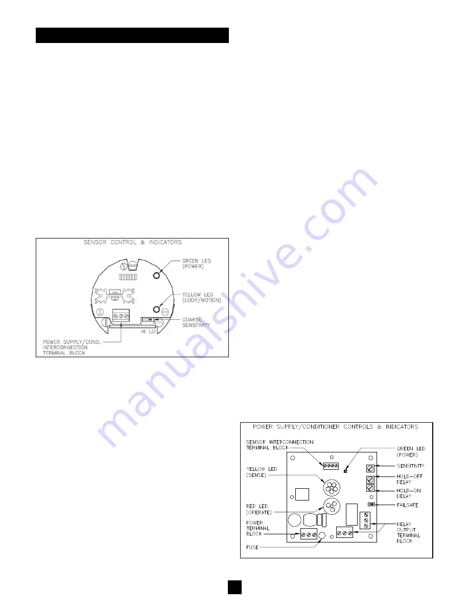
SENSOR
(See Figure 11)
Coarse Sensitivity
- The coarse sensitivity is a slide switch
which permits selection of “HI” or “LO” settings. This selection
operates in tandem with the main sensitivity adjustment found in
the power supply/conditioner. The sensor is provided with the
coarse sensitivity switch placed in the “LO” setting which will sat-
isfy most applications. The status of the coarse sensitivity can
be changed to “HI” if the adjustability range found on the power
supply/conditioner is inadequate. (See Calibration of Power
Supply/Conditioner.)
SENSOR INDICATORS
1) Green LED
- Illumination of the Green LED indicates that
power is properly connected to the sensor. Lack of illumination
could be from lack of supplied power or reversing the polarity of
the input connections.
2) Yellow LED
- Any illumination of the Yellow LED indicates that
the “SIG” connection loop is correctly installed. Lack of illumi-
nation could be from improper connection between the sensor
and power supply/conditioner. Detected motion will cause the
Yellow LED to more intensely illuminate.
CALIBRATION
Figure 11
Figure 12
2) Material Density in the Pipe/Chute
- As more product is
placed in motion, the amount of disturbance which is analyzed
as motion also increases. Thus, applications which have signif-
icant material flow can tolerate a lower sensitivity setting then
those applications with minimal material flow.
3) Material Dielectric Constant
- Microwave propagation is
affected by the dielectric constant of the material being sensed.
Typically, low dielectric materials tend to absorb/pass the energy
while high dielectrics tend to reflect the energy. The SFD-2 will
sense material better when energy is reflected. Therefore, low
dielectric materials (i.e. plastics, soap, cement) will require a
greater sensitivity setting than high dielectric materials (i.e.
grains, feed, ores)
4) Material Particle Size
- Microwaves have a particular wave-
length and therefore are more easily reflected when hitting larg-
er particle sizes. Thus, applications with small particle sizes (i.e.
powders) will require a greater sensitivity setting than large par-
ticle sizes (i.e. granulars).
5) Mounting Environment
- When microwave energy is
entrapped within metal containers, internal reflections are pro-
duced therefore creating a increased probability to see material
motion. Thus applications utilizing metallic pipes/chutes require
a lower sensitivity setting than applications utilizing non-metallic
pipes/chutes. Also, since microwave energy losses its power
density with respect to traveled distance, applications utilizing
small diameter pipes/chutes require a lower sensitivity setting
than applications utilizing large diameter pipes/chutes.
2-STEP CALIBRATION
1) While the system is operating (conveyors, augers, etc.) but no
material is flowing, rotate the sensitivity adjustment clockwise
until the “sense” (Yellow) LED illuminates. Note the adjustment
position. (On most applications, this will occur near the 4 o’clock
position).
2) With the material flowing, rotate the adjustment counter-clock-
wise until the “sense” (Yellow) LED turns off. Note the adjust-
ment position. Reposition the sensitivity adjustment at the
halfway point between the LED “on” and LED “off” settings.
(NOTE: If the difference between the two conditions is very
small, thereby making final calibration difficult, reposition the
sensor’s coarse sensitivity setting to the “HI” position and repeat
the 2-Step Calibration procedure. (See Calibration of the
Sensor.) In general, applications which are difficult to sense will
require a greater clockwise setting.
POWER SUPPLY/CONDITIONER
(See Figure 12)
Sensitivity
- A single-turn potentiometer is used to adjust how
sensitive the SFD-2 will be to objects in motion. The poten-
tiometer permits adjustment between the 7 o’clock and 5 o’clock
positions (300 degrees of rotation). Physical stops exist at both
extremes of the adjustment. A fully counter-clockwise adjust-
ment (7 o’clock) creates a very insensitive setting where nearly
all motion is ignored. A fully clockwise adjustment (5 o’clock)
creates the greatest sensitivity. In addition, this setting forces the
power supply/conditioner into the “sense” condition regardless of
motion presence. Ideal adjustment can be achieved via a sim-
ple “2-Step Calibration” procedure. The setting and the ability of
the SFD-2 to sense material is influenced by the mechanical
mounting (See Pre-Installation Considerations) as well as mate-
rial characteristics such as velocity, flow density, dielectric con-
stant, and particle size.
1) Material velocity
- Electronic signal conditioning enables
the sensor to see faster moving material easier than slow mov-
ing material. This is particularly important when distinguishing
between typical material movement and extraneous influences
such as augers, conveyors, etc. Generally, the slower the mate-
rial movement, the greater the sensitivity setting must be.